


c
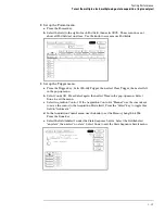
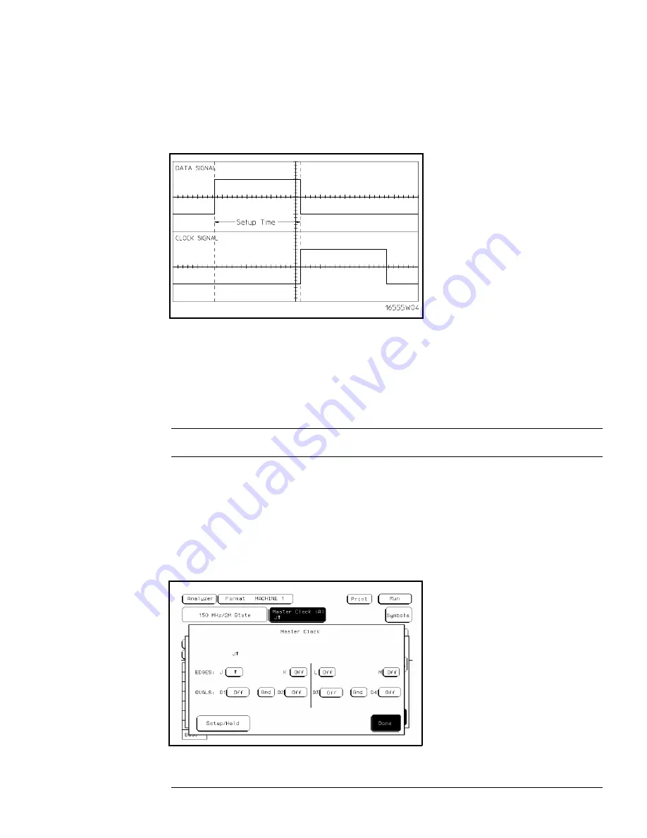
On the oscilloscope, select [Shift]
∆
Time, then select [Enter] to display the setup time
(
∆
Time(1)-(2)).
d
Adjust the pulse generator channel 1 Delay until the pulses are aligned according the
the setup time of the setup/hold combination selected, +0.0 ps or -100 ps.
Disregard the oscilloscope Period(2) value. The settings provided in this procedure
measure the period from falling edge to falling edge, which is not a valid measurement.
4
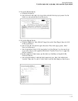
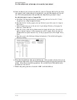
Select the clock to be tested.
a
In the Master Clock menu, select the clock field to be tested, then select the clock
edge as indicated in the table. The first time through this test, use the top clock and
edge in the following table.
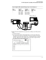
Clocks
J
↑
K
↑
L
↑
M
↑
b
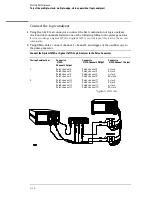
Connect the clock to be tested to the pulse generator channel 1 output.
c
Select Done to exit the Master Clock menu.
Testing Performance
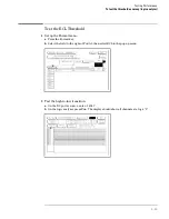
To test the single-clock, single-edge, state acquisition (logic analyzer)
3–25
Содержание 1670G Series
Страница 20: ...1 12...
Страница 116: ...Testing Performance Performance Test Record pattern generator 3 92...
Страница 126: ...Calibrating and Adjusting To test the CAL OUTPUT ports 4 10...
Страница 166: ...Exploded View of the Agilent 1670G series logic analyzer Replacing Assemblies 6 4...
Страница 186: ...Exploded View Exploded view of the Agilent 1670G series logic analyzer Replaceable Parts Exploded View 7 4...
Страница 197: ...The Logic Acquisition Board Logic Acquisition Board Block Diagram Theory of Operation The Logic Acquisition Board 8 7...
Страница 200: ...The Oscilloscope Board Oscilloscope Board Block Diagram Theory of Operation The Oscilloscope Board 8 10...
Страница 201: ...Theory of Operation The Oscilloscope Board 8 11...


