


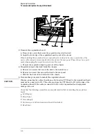


To remove and replace the GPIB and RS-232-C cables
1
Using previous procedures, remove the following assemblies:
•
Handle
•
Rear Feet
•
Cover
•
Disk Drive Assembly
•
Acquisition Board
•
Rear Panel
2
Remove the two hex standoffs connecting the GPIB cable, then slide the GPIB cable
forward and out of the rear panel.
3
Remove the two hex standoffs connecting the RS-232-C cable, then slide the
RS-232-C cable forward and out of the rear panel.
4
Reverse this procedure to install the GPIB and RS-232-C cables.
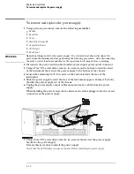
To remove and replace the I/O board
1
Using previous procedures, remove the following assemblies:
•
Handle
•
Rear Feet
•
Cover
•
Disk Drive Assembly
•
Acquisition Board
•
Rear Panel
2
Remove two jackscrews that attach the parallel printer (Centronics) port to the rear
panel.
3
Remove four screws that secure the I/O board to the rear panel.
4
Reverse this procedure to install the I/O board onto the rear panel.
Replacing Assemblies
To remove and replace the GPIB and RS-232-C cables
6–19
Содержание 1670G Series
Страница 20: ...1 12...
Страница 116: ...Testing Performance Performance Test Record pattern generator 3 92...
Страница 126: ...Calibrating and Adjusting To test the CAL OUTPUT ports 4 10...
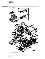
Страница 166: ...Exploded View of the Agilent 1670G series logic analyzer Replacing Assemblies 6 4...
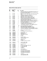
Страница 186: ...Exploded View Exploded view of the Agilent 1670G series logic analyzer Replaceable Parts Exploded View 7 4...
Страница 197: ...The Logic Acquisition Board Logic Acquisition Board Block Diagram Theory of Operation The Logic Acquisition Board 8 7...
Страница 200: ...The Oscilloscope Board Oscilloscope Board Block Diagram Theory of Operation The Oscilloscope Board 8 10...
Страница 201: ...Theory of Operation The Oscilloscope Board 8 11...


