


To test the single-clock, single-edge, state acquisition
(logic analyzer)
Testing the single-clock, single-edge, state acquisition verifies the performance of the
following specifications:
•
Minimum master-to-master clock time
•
Maximum state acquisition speed
•
Setup/Hold time for single-clock, single-edge, state acquisition
This test checks two combinations of data channels using a single-edge clock at two
selected setup/hold times.
Equipment Required
Equipment
Critical Specifications
Recommended Model/Part
Pulse Generator
150 MHz 3.0 ns pulse width, < 600 ps rise time
8133A option 003
Digitizing Oscilloscope
≥
6 GHz bandwidth, < 58 ps rise time
54750A w/ 54751A
Adapter
SMA(m)-BNC(f)
1250-1200
SMA Coax Cable (Qty 3)
18 GHz bandwidth
8120-4948
Coupler
BNC(m)(m)
1250-0216
BNC Test Connector,
6x2 (Qty 4)
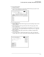
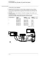
Set up the equipment
1
Turn on the equipment required and the logic analyzer. Let them warm up for
30 minutes before beginning the test if you have not already done so.
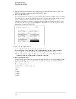
2
Set up the pulse generator.
a
Set up the pulse generator according to the following table.
Pulse Generator Setup
Timebase
Channel 2
Period
Channel 1
Mode: Int
Mode: Pulse
Divide: Divide
÷
2
Mode: Square
Period: 6.666 ns
Divide: PULSE
÷
2
Ampl: 0.50 V
Delay: 0.000 ns
Width: 3.000 ns
Offs: 0.00 V
High:
−
0.90 V
High:
−
0.90 V
Low:
−
1.70 V
Low:
−
1.70 V
b
Disable the pulse generator channel 1 COMP (with the LED off).
3–17
Содержание 1670G Series
Страница 20: ...1 12...
Страница 116: ...Testing Performance Performance Test Record pattern generator 3 92...
Страница 126: ...Calibrating and Adjusting To test the CAL OUTPUT ports 4 10...
Страница 166: ...Exploded View of the Agilent 1670G series logic analyzer Replacing Assemblies 6 4...
Страница 186: ...Exploded View Exploded view of the Agilent 1670G series logic analyzer Replaceable Parts Exploded View 7 4...
Страница 197: ...The Logic Acquisition Board Logic Acquisition Board Block Diagram Theory of Operation The Logic Acquisition Board 8 7...
Страница 200: ...The Oscilloscope Board Oscilloscope Board Block Diagram Theory of Operation The Oscilloscope Board 8 10...
Страница 201: ...Theory of Operation The Oscilloscope Board 8 11...


