November, 2018 Rev.1.4
109
0
No IRI input is generated
1
IRI interrupt is generated on the condition by IREDGE[1:0]
bits
IREDGE[1:0]
Select IRI interrupt triggering condition.
00
IRI interrupt is disabled
01
Interrupt is triggered on falling edge of IRI input
10
Interrupt is triggered on rising edge of IRI input
11
Interrupt is triggered on both edge of IRI input
IRPOL
Select the polarity of WT input source.
0
The inverted signal from IRAMP output(=COMP_OUT) or
SENSOR/P31 input becomes the input source of WT.
1
The multiplexed output of IRAMP output(=COMP_OUT) or
SENSOR/P31 input becomes the input source of WT.
SINGLE
Select carrier capture numbers. Used with the PHASE bit.
0
Capture continuously until WTIR overflows(=WTIR reaches
to pre-defined value, WTDR1 and WTDR0)
1
Capture first 3 edges of carrier signal
PHASE
Select carrier capture sequence. Used with the SINGLE bit.
0
Capture sequence is 1
st
Falling
Rising
Falling edge
1
Capture sequence is 1
st
Rising
Falling
Rising edge
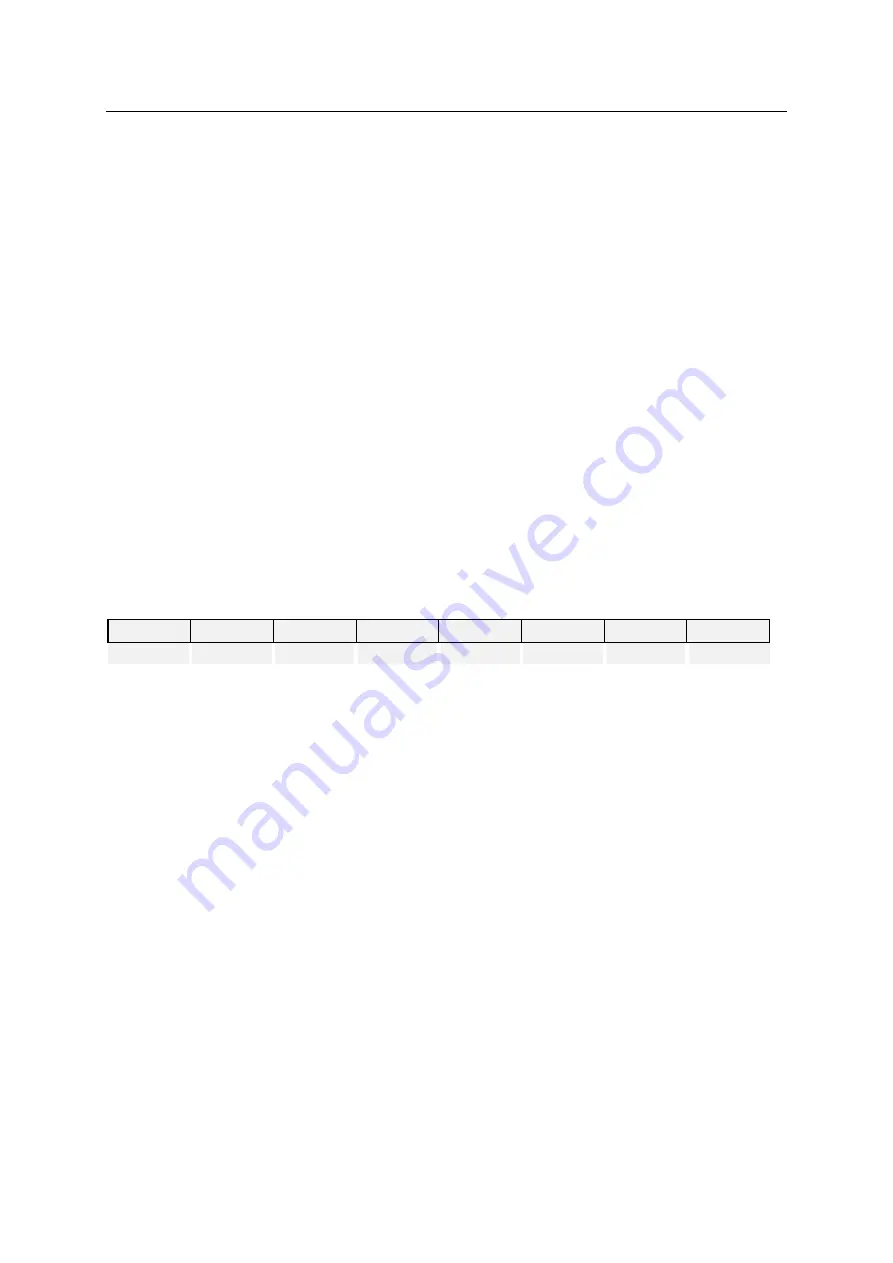
IRCC2 (IR Capture Register 2)
DF
H
7
6
5
4
3
2
1
0
T3IR
T2IR
-
-
T3EDGE1
T3EDGE0
T2EDGE1
T2EDGE0
R/W
R/W
-
-
R/W
R/W
R/W
R/W
Initial value : 00
H
T3IR
Make T3 to calculate the number of incoming carrier signal if CAP3
bit in T3CR bit is not ‘1’.
0
Timer 3 is in normal operation
1
Timer 3 calculates the number of incoming carrier signals.
T2IR
Make T3 to calculate the number of incoming carrier signal if CAP3
bit in T3CR bit is not ‘1’.
0
Timer 2 is in normal operation
1
Timer 2 calculates the number of incoming carrier signals.
T3EDGE[1:0]
Select capture edge when T3 is used for envelop detection of
incoming carrier signal. These bits should be cleared to ‘00’ when
T3 operates in normal capture mode, or the WT output becomes
capture source of Timer 3. The T3IR bit should be cleared to ‘0’
also.
00
No capture
01
Falling edge
10
Rising edge
11
Both edge
T2EDGE[1:0]
Select capture edge when T2 is used for envelop detection of
incoming carrier signal. These bits should be cleared to ‘00’ when
T2 operates in normal capture mode, or the WT output becomes
capture source of Timer 2. The T2IR bit should be cleared to ‘0’
also.
00
No capture
01
Falling edge
10
Rising edge
Содержание MC96FR364B
Страница 17: ...MC96FR364B November 2018 Rev 1 4 17 4 PACKAGE DIMENSION...
Страница 18: ...MC96FR364B 18 November 2018 Rev 1 4 Figure 4 1 PKG DIMENSION 28 TSSOP...
Страница 23: ...MC96FR364B November 2018 Rev 1 4 23 6 3 REMOUT Port Data PAD VDD Figure 6 3 REMOUT port...
Страница 69: ...November 2018 Rev 1 4 69 Initial value 00H BIT 7 0 BIT counter value...


