


Program features
115
As seen in the state diagram, the brake Open command is triggered when the drive
comes to the run mode after the motor gets magnetised. The drive waits for the
Torque proving ok signal and then releases the brake Open command, which
switches on the brake open relay output. Any rotation of the motor above the allowed
motor slip speed during the torque generation will result in a brake slip fault. The
drive waits for the period of the brake open delay for the brake to get opened
mechanically. The drive supervises for a brake fault if the brake does not open within
the period of the brake open delay time. If the brake open delay has elapsed, the
drive moves on to the next state for the releasing of the speed reference.
The (
) EXTEND RUN T can be used when the start request is released within a
short span on receiving the Stop command. The drive keeps the motor magnetised
for the extended time, and thereby reduces the next start sequence time. In the local
control mode, the extended run time can be stopped by pressing the CDP stop
button twice. The second stop request should be given when the drive is in the
extended time period.
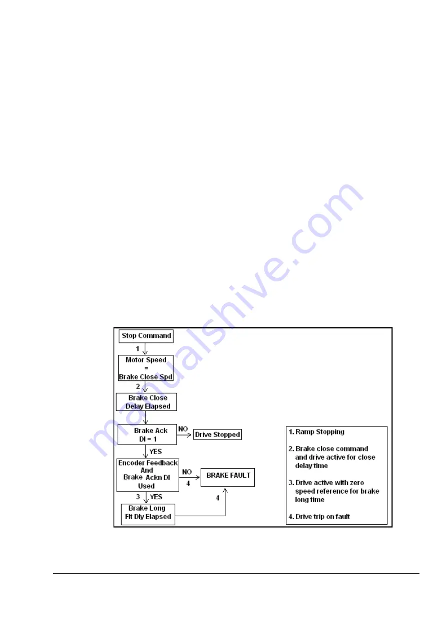
The (
) BRK LONG FLT DLY can be used for safety purposes if the brake is not
closed properly in the stopping sequence. The delay is applicable only when
encoder feedback is used and when the brake acknowledge is configured to a DI.
The drive checks for the brake acknowledge signal during the stopping sequence. If
the signal remains ON after the brake close delay (Par.
) has elapsed, the drive
keeps the torque ON to the motor for the brake long fault delay period. This ensures
that the drive does not trip immediately and drops the load. During the brake long
fault delay period, a signal (
bit 9) is activated which can be used for safety
interlocks. If the brake long fault delay has elapsed and the brake acknowledge is
still ON, the drive trips on a brake fault. See the figure below.
Содержание ACS 800 Series
Страница 1: ...ACS800 Firmware Manual Crane Control Program N697 ...
Страница 4: ......
Страница 26: ...Start up and control through the I O interface 26 ...
Страница 36: ...Quick start up guide 36 ...
Страница 52: ...Control panel 52 ...
Страница 105: ...Program features 105 Figure Control diagram for Shaft synchronisation executed in 20 ms ...
Страница 126: ...Program features 126 The figures below show speed limits according to different load conditions ...
Страница 128: ...Program features 128 ...
Страница 150: ...Application macros control location EXT1 EXT2 150 ...
Страница 228: ...Actual signals and parameters 228 ...
Страница 299: ...Adaptive Programming examples for crane control 299 ...
Страница 305: ...Adaptive Programming examples for crane control 305 ...
Страница 312: ...Adaptive Programming examples for crane control 312 The following figures show the previous example enlarged ...
Страница 314: ...Adaptive Programming examples for crane control 314 The following figures show the previous example enlarged ...
Страница 318: ...Analogue Extension Module 318 ...
Страница 332: ...Additional data actual signals and parameters 332 ...
Страница 333: ...DriveWindow 333 DriveWindow DriveWindow connected to the ACS800 RMIO RDCO board and channel CH3 ...
Страница 334: ...DriveWindow 334 ...
Страница 335: ...Control block diagrams 335 Control block diagrams ...
Страница 336: ...Control block diagrams 336 ...
Страница 337: ...Control block diagrams 337 ...
Страница 338: ...Control block diagrams 338 ...
Страница 340: ...www abb com drives www abb com drivespartners Contact us 3AFE68775230 Rev E EN 2012 09 25 ...


