Actual signals and parameters
179
21.08
SCALAR FLY START
Activates the flying start feature in the Scalar control mode. See parameters
NO
Inactive
0
YES
Active
65535
21.09
START INTRL FUNC
Defines how the Start Interlock input on the RMIO board affects the drive
operation.
Note:
In the Master/Follower mode, the settings must be the same in both the
Master and the Follower drives.
OFF2 STOP
Drive running: 1 = Normal operation. 0 = Stop by coasting.
Drive stopped: 1 = Start allowed. 0 = No start allowed.
Restart after OFF2 STOP: Input is back to 1 and the drive receives rising edge
of the Start signal.
1
OFF3 STOP
Drive running: 1 = Normal operation. 0 = Stop by ramp. The ramp time is
defined with parameter 22.07 EM STOP RAMP.
Drive stopped: 1 = Normal start. 0 = No start allowed.
Restart after OFF3 STOP: Start Interlock input = 1 and the drive receives rising
edge of the Start signal.
2
21.10
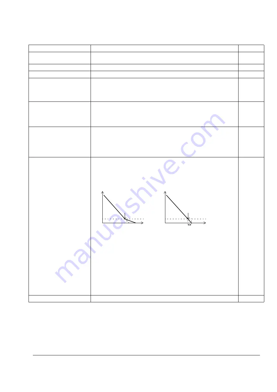
ZERO SPEED DELAY Defines the delay for the zero speed delay function. The function is useful in
applications where a smooth and quick restarting is essential. During the delay
the drive knows accurately the rotor position.
No Zero Speed Delay
The drive receives a Stop command and decelerates along a ramp. When the
motor actual speed falls below an internal limit (called Zero Speed), the speed
controller is switched off. The inverter modulation is stopped and the motor
coasts to standstill.
With Zero Speed Delay
The drive receives a Stop command and decelerates along a ramp. When the
actual motor speed falls below an internal limit (called Zero Speed), the zero
speed delay function activates. During the delay the functions keeps the speed
controller live: the inverter modulates, motor is magnetised and the drive is
ready for a quick restart.
0.0 … 60.0 s
Delay time
10 = 1 s
Index
Name/Selection
Description
FbEq
Speed
Time
Zero Speed
Speed
Time
Zero Speed
Delay
No Zero Speed Delay
With Zero Speed Delay
Speed controller
switched off: Motor
coasts to stop.
Speed controller remains live.
Motor is decelerated to true 0
speed.
Содержание ACS 800 Series
Страница 1: ...ACS800 Firmware Manual Crane Control Program N697 ...
Страница 4: ......
Страница 26: ...Start up and control through the I O interface 26 ...
Страница 36: ...Quick start up guide 36 ...
Страница 52: ...Control panel 52 ...
Страница 105: ...Program features 105 Figure Control diagram for Shaft synchronisation executed in 20 ms ...
Страница 126: ...Program features 126 The figures below show speed limits according to different load conditions ...
Страница 128: ...Program features 128 ...
Страница 150: ...Application macros control location EXT1 EXT2 150 ...
Страница 228: ...Actual signals and parameters 228 ...
Страница 299: ...Adaptive Programming examples for crane control 299 ...
Страница 305: ...Adaptive Programming examples for crane control 305 ...
Страница 312: ...Adaptive Programming examples for crane control 312 The following figures show the previous example enlarged ...
Страница 314: ...Adaptive Programming examples for crane control 314 The following figures show the previous example enlarged ...
Страница 318: ...Analogue Extension Module 318 ...
Страница 332: ...Additional data actual signals and parameters 332 ...
Страница 333: ...DriveWindow 333 DriveWindow DriveWindow connected to the ACS800 RMIO RDCO board and channel CH3 ...
Страница 334: ...DriveWindow 334 ...
Страница 335: ...Control block diagrams 335 Control block diagrams ...
Страница 336: ...Control block diagrams 336 ...
Страница 337: ...Control block diagrams 337 ...
Страница 338: ...Control block diagrams 338 ...
Страница 340: ...www abb com drives www abb com drivespartners Contact us 3AFE68775230 Rev E EN 2012 09 25 ...


