


AEMZP0BA - EPS-AC0 - User Manual
Page - 79/95
10) MOTOR VOLTAGE
It is a percentage. 100% means the sine waves in the motor have the maximum
PWM amplitude.
11) MOTOR CURRENT
Ampere value. Root Mean Square value of the line current in the motor.
12) ENC SPEED
Hertz value with 2 decimal digit. This is the speed of the motor measured with
the encoder on the motor shaft.
13) ENDSTROKE CW
Provides real time the active state (ON) or not of the CW toggle switch
(connected to CNA#3). It is On when CNA#3 is low (see 7.5).
14) ENDSTROKE ACW
Provides real time the active state (ON) or not of the CCW toggle switch
(connected to CNA#2). It is On when CNA#2 is low (see 7.5).
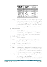
15) CW LIMIT LEVEL
When the maximum angle limitation via feedback sensors is enabled (option
LIMIT DEVICE to ON when FEEDBACK DEVICE is OPTION #1,2,3; 1
ST
ANGLE
COARSE and 2
ND
ANGLE COARSE less than level 9 when FEEDBACK
DEVICE is OPTION #4) and the FEEDBACK ENC overtakes the superior limit
for the steered wheel angle limitation, the steered wheel angle will be limited
and CW LIMIT LEVEL turns ON (active).
16) ACW LIMIT LEVEL
When the maximum angle limitation via feedback sensors is enabled (option
LIMIT DEVICE to ON when FEEDBACK DEVICE is OPTION #1,2,3; 1
ST
ANGLE
COARSE and 2
ND
ANGLE COARSE less than level 9 when FEEDBACK
DEVICE is OPTION #4) and the FEEDBACK ENC is lower than the inferior limit
for the steered wheel angle limitation, the steered wheel angle will be limited
and ACW LIMIT LEVEL turns ON (active).
17) AUTO IN PROGRESS
Provides real time the information the eps-ac0 follows the manual command
(AUTO IN PROGRESS is OFF) or is executing an automatic centering (AUTO
IN PROGRESS is ON).
18) MM ALARM SWITCH
It is On when the safety contact belonging to the main uC is closed.
19) SM ALARM SWITCH
It is On when the safety contact belonging to the slave uC (supervisor) is closed.
20) TRUCK MOVING
It provides the state of the travel demand for driving the truck. This information
is obtained either with the travel demands directly connected to CNA#1 or via
CAN Bus (depending by the state of the CAN BUS setting see 12.4.5.2).
21) HIGH RESOL AD
It turns ON when the set point potentiometer is processed with a high resolution
AD.
Summary of Contents for EPS-AC0
Page 23: ...AEMZP0BA EPS AC0 User Manual Page 23 95 6 2 EPS AC0 Stepper Motor diagram Figure 6 2...
Page 24: ...Page 24 95 AEMZP0BA EPS AC0 User Manual 6 3 EPS AC0 Twin pot diagram Figure 6 3...
Page 55: ...AEMZP0BA EPS AC0 User Manual Page 55 95 12 3 2 RTC with Encoder and Feedback pot Figure 12 3...