


AEMZP0BA - EPS-AC0 - User Manual
Page - 63/95
1) ADJUSTMENT
#01
This setting is used to acquire the motor resistance (see 13.1).
2) SET
CURRENT
This setting is factory adjusted to calibrate the ADJUSTMENT #03 and #04
below.
3) ADJUSTMENT
#02
Motor resistance in milliohms. This is the resistance of the motor measured
between two motor terminals. The motor resistance may be either self-acquired
with the procedure 13.1 or may be set by rolling up or down this adjustment.
4) ADJUSTMENT
#03
(Factory adjusted).
Parameter to
compensate for the gain of the current
amplifier in phase W.
5) ADJUSTMENT
#04
(Factory adjusted). Parameter to
compensate for the gain of the current
amplifier in phase V.
6) SET BATTERY TYPE
Set this adjustment to the nominal battery voltage. Pay attention, never set SET
BATTERY TYPE higher than 36 V for a 24/36 V controller.
7) SET SAT. FREQ.
Set this adjustment to the corner frequency of the motor. SET SAT FREQ is to
be meant as the maximum frequency at which the motor supplies the maximum
torque (it is the superior limit of the constant torque characteristic). Frequency
higher than SET SAT FREQUENCY gets the motor weakened.
8) OVERSAT
FREQ
The maximum motor frequency is set with the sum between SET SAT FREQ
and OVERSAT FREQ. OVERSAT FREQ is the increment, over the SET SAT
FREQUENCY, in which the steering motor works with degraded flux (weakening
area). Default choice is 1 Hz (i.e. the steering motor never works in the
weakening region).
9) MAXIMUM
SLIP
(Factory adjusted). MAXIMUM SLIP modifies the acceleration and deceleration
ramp for the frequency in the motor. Higher MAXIMUM SLIP gets faster
acceleration and deceleration ramp.
If the encoder is used for the motor control (ENCODER CONTROL is On),
MAXIMUM SLIP has another meaning: it is the slip to be applied when the
control is sourcing the maximum current.
10) NO LOAD CURRENT
In order it shall be possible to weaken the steering motor when lightened
(reducing power loss in the motor), it is necessary to specify the current the
motor drains when working full flux and without load (NO LOAD CURRENT). To
find this value it is necessary to set the DEBUG OUTPUT to level 10 (see
12.4.6.4) and to measure the current in the motor when running without load
and a frequency close to SET SAT FREQ/2.
11) AUX VOLTAGE #1
(Factory adjusted). This is the self-acquired offset value of the stepper motor
line connected to CNA#9. The default value is 2.500 mV and can be re-acquired
Summary of Contents for EPS-AC0
Page 23: ...AEMZP0BA EPS AC0 User Manual Page 23 95 6 2 EPS AC0 Stepper Motor diagram Figure 6 2...
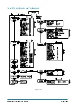
Page 24: ...Page 24 95 AEMZP0BA EPS AC0 User Manual 6 3 EPS AC0 Twin pot diagram Figure 6 3...
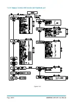
Page 55: ...AEMZP0BA EPS AC0 User Manual Page 55 95 12 3 2 RTC with Encoder and Feedback pot Figure 12 3...