


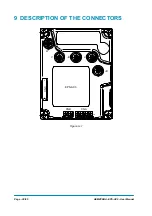


AEMZP0BA - EPS-AC0 - User Manual
Page - 41/95
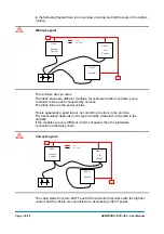
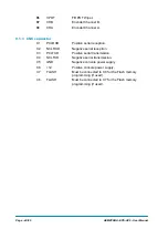
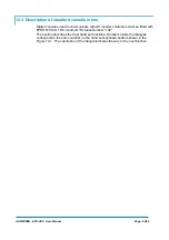
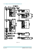
9.2 Description of power connections
View of the power bars:
W
V
-B
U
+B
CNC
1
8
8
5
4
1
8
1
7
14
CNB
CNA
EPS-AC0
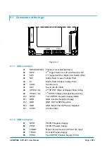
Figure 9–3
-B
Negative of the battery.
+B
Positive of the battery.
U; V; W
Connection bars of the three motor phases; follow this
sequence and the indication on the motor.
Summary of Contents for EPS-AC0
Page 23: ...AEMZP0BA EPS AC0 User Manual Page 23 95 6 2 EPS AC0 Stepper Motor diagram Figure 6 2...
Page 24: ...Page 24 95 AEMZP0BA EPS AC0 User Manual 6 3 EPS AC0 Twin pot diagram Figure 6 3...
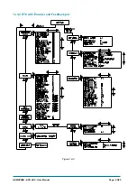
Page 55: ...AEMZP0BA EPS AC0 User Manual Page 55 95 12 3 2 RTC with Encoder and Feedback pot Figure 12 3...