


AEMZP0BA - EPS-AC0 - User Manual
Page - 35/95
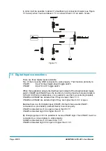
1) Emission
2) Electromagnetic
Immunity
3) ESD
rejection.
U
When possible it is strongly recommended preventing Emission and Immunity
problems by locating the controllers inside a metallic enclosure. In most
cases, a truck with a metallic enclosure will avoid EMC problem.
8.9.1 Emission
Emission
refers to the electromagnetic disturbances that the device generates in
the surrounding space. Countermeasure should be adopted to prevent the
propagation of those disturbances. We talk about “conduction” issues when guiding
structures such wires and cables are involved; “radiated emissions” issues when it is
studied the propagation of electromagnetic energy through the open space. In our
case the origin of the disturbances can be found inside the controller with the
switching of the mosfets which are working at high frequency and generate RF
energy.
Wires and cables are responsible for the spreading of this RF
disturbance because they works as antennas
, so a good layout of the cables and
their shielding can solve the majority of the emission problems.
Three ways can be followed to reduce the emissions:
1) SOURCE OF EMISSIONS: finding the main source of disturbs and works on it.
2) SHIELDING: enclosing contactor and controller in a shielded box; using
shielded cables.
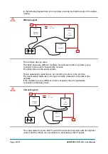
3) LAYOUT: a good layout of the cables can minimize the antenna effect; cables
running nearby the truck frame or in iron channels connected to truck frame is
generally a suggested not expensive solution to reduce the emission level.
8.9.2 Electromagnetic
Immunity
The
electromagnetic immunity
concerns the susceptibility of the controller to
external electromagnetic fields and their influence on its correct work made.
These tests are carried out at determined levels of electromagnetic fields, to
simulate external undesired disturbances and verify the electronic device response.
Here are some suggestions to improve the electromagnetic immunity:
1) SHIELDING: enclosing controller and wiring when possible on a shielded box;
using shielded cables.
2) LAYOUT: hide the exposed wires, which are connected to the controller, behind
metallic part working like natural barriers.
3) FERRITES: embrace the exposed wires, connected to the controller, with a split
or solid ferrite.
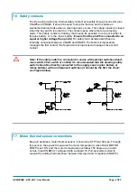
4) BY-PASS CAPACITOR: connect an interference suppression capacitor (Y type)
between the minus battery and the truck frame, as close as possible to the
controller.
8.9.3 ESD
When an accumulation of charge occurs in a part insulated from the ground, it may
discharging in a shot when turning in contact with a part having different potential.
This phenomenon is called Electrostatic Discharge (ESD).
In forklift trucks applications, special attention should be adopted for avoiding ESD.
The main rule is that it is always much easier and cheaper to avoid ESD from
being generated, than to increase the level of immunity of the electronic
devices.
Summary of Contents for EPS-AC0
Page 23: ...AEMZP0BA EPS AC0 User Manual Page 23 95 6 2 EPS AC0 Stepper Motor diagram Figure 6 2...
Page 24: ...Page 24 95 AEMZP0BA EPS AC0 User Manual 6 3 EPS AC0 Twin pot diagram Figure 6 3...
Page 55: ...AEMZP0BA EPS AC0 User Manual Page 55 95 12 3 2 RTC with Encoder and Feedback pot Figure 12 3...