


AEMZP0BA - EPS-AC0 - User Manual
Page - 27/95
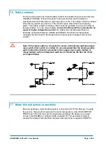
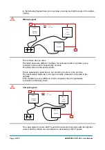
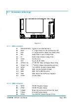
7.6 Safety contacts
The Eps-ac0 provides an internal safety contact accessible through connector pins
CNA#5 and CNA#4. It should be used to stop the traction and to enable an
electromechanical brake when a steering alarm occurs. This safety contact is closed
when the key switch is turned on. The contact opens where there is a steering
alarm. This safety contact is floating, that means it's possible to connect it either to
the plus battery or to the minus battery.
Ensure that the pin #5 is connected to an
equal or higher voltage than pin #4.
For safety two cascaded switches are
internally connected between CNA#5 and CNA#4. The Main microprocessor
manages the first contact; the Supervisor microprocessor manages the second
contact.
U
Note: If the safety switch is connected in series with external switches (dead-
man switch, tiller switch or similar) it's recommended that the steering safety
switch should be directly connected to the supply source (plus battery or
minus battery) with no interposed switches (it should be the first the chain:
see Figure below).
7.7 Motor thermal sensor connections
Eps-ac0 handles a motor thermal sensor: it should be KTY184-130 type. Through
this sensor, the eps-ac0 measures the motor temperature: when DIAG MOTOR
TEMP is set ON, and the motor temperature overtakes 150 degrees, an alarm
occurs. Input CNB#3 is configured with a aboard 1K Pull-up resistor suited to
receive the analog thermal sensor between this input and a negative (CNA#13).
Summary of Contents for EPS-AC0
Page 23: ...AEMZP0BA EPS AC0 User Manual Page 23 95 6 2 EPS AC0 Stepper Motor diagram Figure 6 2...
Page 24: ...Page 24 95 AEMZP0BA EPS AC0 User Manual 6 3 EPS AC0 Twin pot diagram Figure 6 3...
Page 55: ...AEMZP0BA EPS AC0 User Manual Page 55 95 12 3 2 RTC with Encoder and Feedback pot Figure 12 3...