


Page - 18/95
AEMZP0BA - EPS-AC0 - User Manual
It is handled this way:
1) At key-on, the eps-ac0 turns the steering motor moving in either CW or CCW
side, according to whether the output level from the straight ahead switch is high
or low (in the above sketch a proximity sensor is used as a straight ahead
switch).
2) When the falling edge on the prox switch is detected, the encoder counting is
initialized to 0 and the steered wheel is centered.
3) Then the encoder counting is continuously updated to measure the steered
wheel angle.
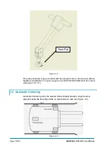
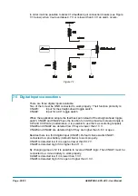
At key on, the Iron plate (with the shape shown in Figure 4-6), provides the correct
direction in which the eps-ac0 must turn the steering motor in order the falling edge
on the proximity switch is detected.
An option POT UP SW1 EDGE (see 12.4.1.12) determines the direction where the
steered wheel rotates to seek the straight ahead switch (i.e. it specifies if the steered
wheel at the initial alignment is oriented with the iron plate in its right or left side).
Together with the straight-ahead switch, a second toggle switch could be adopted to
detect when the steered wheel is in the 90 degrees limiting position. This second
toggle switch must be connected to CNA#2 and GND (minus battery).
Iro n P la te
S te e re d w h e e l
P ro x s w itc h
9 0 ° P ro x s w itc h
Figure 4-7
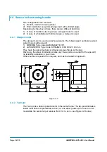
4.5.3 Feedback
Encoder
One big advantage of our eps-ac0 controller is that it can work with a cost-effective
very low-resolution encoder. Our competitors normally need a sensor bearing with
32 or higher pulses/rev; our eps-ac0 works also with a cheap encoder having 4
pulses/rev. That is more than enough for the angle measurement: in fact, with a total
reduction of 1:200 and a 4 pulses/revs resolution, we have 1600 events (encoder
transitions) within 180° of the steered angle. So the angle measurement is
determined with quanta of 180/1600=0.112 degrees. This is possible because our
patent system does not use the encoder for the AC motor control; it works
completely sensorless.
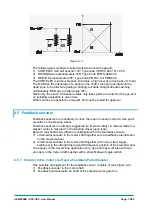
Following this statement, we have developed, together with a Zapi’s partner AC-
motor-brand, a 4 pulses/rev discrete encoder. It is an external device (not integrated
in the ball bearing) mounted in the backside of the motor (see Figure 4.8 below
showing a 300 W AC Motor by “Best Motor” brand). The advantages of this solution
are both, money saving and effective time saving in case of encoder replacement.
Summary of Contents for EPS-AC0
Page 23: ...AEMZP0BA EPS AC0 User Manual Page 23 95 6 2 EPS AC0 Stepper Motor diagram Figure 6 2...
Page 24: ...Page 24 95 AEMZP0BA EPS AC0 User Manual 6 3 EPS AC0 Twin pot diagram Figure 6 3...
Page 55: ...AEMZP0BA EPS AC0 User Manual Page 55 95 12 3 2 RTC with Encoder and Feedback pot Figure 12 3...