


AEMZP0BA - EPS-AC0 - User Manual
Page - 33/95
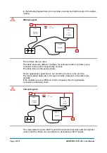
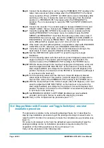
Otherwise, if two controllers are similar in power (for example a traction and a
pump motor controller) and a third module works with less current, the best way
to deal this configuration is to create a common ground point (star configuration)
U
Correct Layout:
In this case the power cables starting from the two similar controllers must be as
short as possible. Of course also the diameter of the cable concurs in the voltage
drops described before (higher diameter means lower impedance). So, in this last
example, the cable between the minus of the Battery and the common ground point
(pointed by the arrow in the image) must dimensioned taking into account thermal
and voltage drop problems.
4
Can advantages
The complexity of today systems needs more and more data, signal and information
must flow from a node to another. CAN is the solution to different problems that
arise from this complexity
- simplified design (readily available, multi sourced components and tools)
- lower costs (less and smaller cables )
- improved reliability (fewer connections)
- analysis of problems improved (easy connection with a pc to read the data flowing
through the cable).
8.7 Wiring: I/O connections
After crimping the cable, verify that all strands are entrapped in the wire barrel.
Verify that all the crimped contacts are completely inserted on the connector
cavities. For information about the mating connector pin assignment see the
description of the connectors in topic 9.
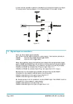
Node 1
Traction
Control
Node 2
Lift
Control
Node 3
eps-ac0
R
R
Can Bus
Power cables
Center of the Ground Connections
Summary of Contents for EPS-AC0
Page 23: ...AEMZP0BA EPS AC0 User Manual Page 23 95 6 2 EPS AC0 Stepper Motor diagram Figure 6 2...
Page 24: ...Page 24 95 AEMZP0BA EPS AC0 User Manual 6 3 EPS AC0 Twin pot diagram Figure 6 3...
Page 55: ...AEMZP0BA EPS AC0 User Manual Page 55 95 12 3 2 RTC with Encoder and Feedback pot Figure 12 3...