


AEMZP0BA - EPS-AC0 - User Manual
Page - 45/95
position. If present, the minimum of the FB ENC is recorded too (although it
is not shown in the hand set).
Step16
Set FEEDBACK DEVICE to OPTION#3 (feedback pot, feedback encoder
and straight ahead toggle switch) and recycle the key to enable the steering
by encoder.
Step17
When FEEDBACK DEVICE is OPTION #3, it is necessary to seek a falling
edge on the SW1 (CNA#3) corresponding at the straight ahead position.
This is done by moving the steered wheel toward a falling edge of the
straight ahead switch. Depending by the shape of the iron plate to act the
straight ahead sensor, the falling edge may occur either in a CW or in a
CCW rotation. If the iron plate in your arrangement generates a sole rising
edge in present steering direction, it is possible to reverse the turning
direction of the steered wheel during the initial alignment. To do that an
OPTIONS called POT UP SW1 EDGE is supplied. When it is ON, the
steered wheel seeks the falling edge during an initial automatic rotation in
the direction of an increasing FB POT. When it is OFF, the steered wheel
seeks the falling edge during an initial automatic rotation in the direction of a
decreasing FB POT. (A properly setting of POT UP SW1 EDGE is required
to avoid EPS NOT ALIGN alarm).
Step18
When FEEDBACK DEVICE is OPTION #3, it is necessary to autoacquire
the FB POT value at the matching with the falling edge on the straight
ahead switch (SW1). To do that, enter the SET FBPOT AT SW1 setting in
the adjustments menu. Save and recycle the key. After the acquisition, the
SET FBPOT AT SW1 value should be close to the 2.5 V value; otherwise it
is necessary to re-make the FB POT mounting in such a way its wiper is
close to 2.5 V at the matching with the falling edge on SW1.
Step19
Carry out the complete set-up procedure (see 11.1).
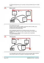
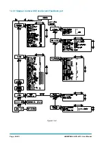
10.3 Stepper Motor with Encoder and Feedback pot: one shot
installation procedure
This procedure is relative to the connecting drawings Figure 6-2. It describes the
step by step installation procedure to get the prototype working in manual mode: to
raise the AUTC function it is necessary to make the complete set-up procedure (see
topic 11).
For every truck released on the field, the default set-up shall reply the prototype
settings and so no installation procedure is required except for the acquisition of the
limiting position (see the quick set-up 11.2).
Carry out the procedure in the following order.
Step1
Connect the AC motor phases in such a way the phase references U, V, W
on the steering motor correspond to the terminals references (U, V, W) on
the eps-ac0.
Step2
In the SET MODEL menu set the SYSTEM CONFIG setting to LEVEL 0 to
steer in open loop with a stepper motor in manual mode. Turn off and on the
key in order the setting is acquired.
Step3
Set the FEEDBACK DEVICE to OPTION #1 to specify your feedback
solution is the sole FEEDBACK POT. Switch off the key after the change. (It
is necessary to start with the sole feedback pot to avoid a POSITION
ERROR due to the unknown scaling between the encoder counting and the
feedback pot value before of an encoder learning operation - Step 12 and
14 below).
Step4
Set option ENCODER CONTROL to OFF.
Summary of Contents for EPS-AC0
Page 23: ...AEMZP0BA EPS AC0 User Manual Page 23 95 6 2 EPS AC0 Stepper Motor diagram Figure 6 2...
Page 24: ...Page 24 95 AEMZP0BA EPS AC0 User Manual 6 3 EPS AC0 Twin pot diagram Figure 6 3...
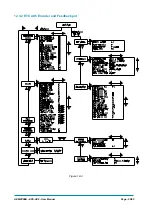
Page 55: ...AEMZP0BA EPS AC0 User Manual Page 55 95 12 3 2 RTC with Encoder and Feedback pot Figure 12 3...