


AEMZP0BA - EPS-AC0 - User Manual
Page - 43/95
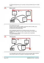
positive). Then it is necessary to swap the PPOT with NPOT (CNB#2 with
CNB#1).
Step6
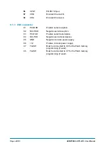
Connect the encoder. The encoder supply is between CNB#4 (5Vdc) and
CNA#11 (GND): the two channels are CNB#8 (CHA) and CNB#7 (CHB).
Step7
Verify the reading ENC SPEED in the tester menu is consistent with the
reading FREQUENCY in the tester menu. Consistent means that ENC
SPEED and FREQUENCY must have the same sign and a close value. If
ENC SPEED has a wrong sign, swap CHA (CNB#8) with CHB (CNB#7). If
ENC SPEED is not close to FREQUENCY, the encoder resolution is wrong
and a different SW is needed (see 12.4.7.12 and 12.4.7.8).
Step8
If the motor runs well without glitches, it is possible to stays with ENCODER
CONTROL to OFF; otherwise, turn ENCODER CONTROL to ON.
Step9
Verify the steered wheel rotates in the correct direction according to the
hand wheel. If it isn’t, swap CPOC1 (CNA#9) with CPOC2 (CNA#8).
Step10
Set the LIMIT DEVICE option to OFF to avoid the maximum angle
limitations.
Step11
Set NUMBNESS parameters to Level 0.
Step12
Move the hand wheel until the maximum (plus 90 degrees) steered wheel
angle is achieved (Increase 1ST ANGLE COARSE - and FINE - if
necessary). This position (plus 90 degrees) corresponds to the maximum
value of the FEEDBACK POT reading in the TESTER menu.
Step13
With the steered wheel in the maximum angle (plus 90 degrees), enter and
save the adjustment SET MAX FB POT on the hand set to memorize the
steer angle feedback pot voltage for the maximum (plus 90 degrees) limit
position. If present, the maximum of the FB ENC is recorded too (although it
is not shown in the hand set).
Step14
Move the steering wheel until the minimum (minus 90 degrees) steered
wheel angle is achieved (Increase 2ND ANGLE COARSE - and FINE - if
necessary). This position (minus 90 degrees) corresponds to the minimum
value of the FEEDBACK POT reading in the TESTER menu.
Step15
With the steered wheel in the minimum angle (minus 90 degrees), enter and
save the adjustment SET MIN FB POT on the hand set to memorize the
steer angle feedback pot voltage for the minimum (minus 90 degrees) limit
position. If present, the minimum of the FB ENC is recorded too (although it
is not shown in the hand set).
Step16
Set FEEDBACK DEVICE to OPTION#2 (feedback pot plus feedback
encoder) and recycle the key to enable the steering by encoder.
Step17
Carry out the complete set-up procedure (see 11.1).
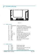
10.2 Twin Pot with Encoder, Straight Ahead Switch and Feedback pot:
one shot installation procedure
This procedure is relative to a feedback sensor arrangement consisting of a straight
ahead switch, together with the feedback potentiometer and the encoder. This
configuration is not much spread. It is useful to have a redundancy in the
initialization of the encoder (without straight ahead switch, the feedback encoder is
initialized by using the feedback pot only) and a better precision in the straight
ahead matching (the feedback pot mounting normally has a dead zone). It describes
the step by step installation procedure to get the prototype working in manual mode:
to raise the AUTC function it is necessary to make the complete set-up procedure
(see topic 11).
Summary of Contents for EPS-AC0
Page 23: ...AEMZP0BA EPS AC0 User Manual Page 23 95 6 2 EPS AC0 Stepper Motor diagram Figure 6 2...
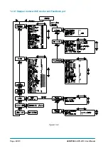
Page 24: ...Page 24 95 AEMZP0BA EPS AC0 User Manual 6 3 EPS AC0 Twin pot diagram Figure 6 3...
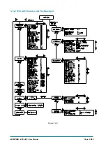
Page 55: ...AEMZP0BA EPS AC0 User Manual Page 55 95 12 3 2 RTC with Encoder and Feedback pot Figure 12 3...