


Page - 32/95
AEMZP0BA - EPS-AC0 - User Manual
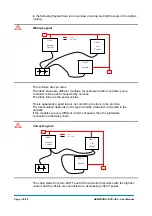
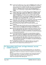
In the following figures there is an overview of wrong and right layouts of the cables
routing.
U
Wrong Layout:
The red lines are can wires.
The black boxes are different modules, for example traction controller, pump
controller and eps-ac0 connected by can bus.
The black lines are the power cables.
This is apparently a good layout, but can bring to errors in the can line.
The best solution depends on the type of nodes (modules) connected in the
network.
If the modules are very different in terms of power, then the preferable
connection is the daisy chain.
U
Correct Layout:
The chain starts from the –BATT post of the controller that works with the highest
current, and the others are connected in a decreasing order of power.
Node 1
Traction
Control
Node 2
Lift
Control
Node 3
eps-ac0
R
R
Can Bus
Power cables
Node 1
Traction
Control
Node 2
Lift
Control
Node 3
eps-ac0
R
R
Can Bus
Power cables
Summary of Contents for EPS-AC0
Page 23: ...AEMZP0BA EPS AC0 User Manual Page 23 95 6 2 EPS AC0 Stepper Motor diagram Figure 6 2...
Page 24: ...Page 24 95 AEMZP0BA EPS AC0 User Manual 6 3 EPS AC0 Twin pot diagram Figure 6 3...
Page 55: ...AEMZP0BA EPS AC0 User Manual Page 55 95 12 3 2 RTC with Encoder and Feedback pot Figure 12 3...