


Page - 28/95
AEMZP0BA - EPS-AC0 - User Manual
8 INSTALLATION: SUGGESTIONS AND
CAUTIONS
Read and respect the following suggestions to avoid problem during installation and
in the definitive releasing.
8.1 Thermal consideration
1) The heat generated by the power block must be dissipated. For this to be
possible the compartment must be ventilated and the heat sink materials ample.
2) Normally eps-ac0 does not ask for a forced ventilation: if the cooling is poor, a
possible solution could be to redirect a part of the forced air flow of the traction
controller toward the eps-ac0.
3) Abnormal ambient air temperatures should be considered. In situations where
either ventilation is poor, or heat exchange is difficult, forced air ventilation
should be used.
4) The thermal energy dissipated by the power block module varies and is
dependent on the current drawn and the duty cycle.
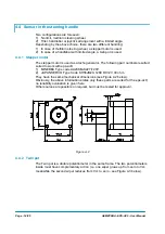
8.1.1 Controller with Base Plate
Installs the controller with the base-plate on a flat metallic surface that is clean and
unpainted; suggested characteristics are: planarity 0.05 mm and roughness 1.6 µm
Apply a light layer of thermo-conductive grease between the two surfaces to permit
better heat dissipation.
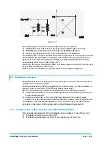
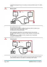
8.1.2 Controller
with finned Heatsink
Sometimes the base plate installation cannot be adopted. Due to positioning
problems or to a low thickness truck frame, it is necessary to adopt a finned
dissipation combined with one or more fans.
1) The air flux should hit the fins directly, to maximize the cooling effect.
2) In addition to fans, also air-ducting systems can be used to maintain low the
temperature of the controller.
3) It is necessary to ensure that cold air is taken from outside the controller
compartment and hot air is easily pushed away from the controller
compartment.
4) It is mandatory to avoid that the cooling air is re-circulated inside the controller
compartment.
Summary of Contents for EPS-AC0
Page 23: ...AEMZP0BA EPS AC0 User Manual Page 23 95 6 2 EPS AC0 Stepper Motor diagram Figure 6 2...
Page 24: ...Page 24 95 AEMZP0BA EPS AC0 User Manual 6 3 EPS AC0 Twin pot diagram Figure 6 3...
Page 55: ...AEMZP0BA EPS AC0 User Manual Page 55 95 12 3 2 RTC with Encoder and Feedback pot Figure 12 3...