


Page - 40/95
AEMZP0BA - EPS-AC0 - User Manual
B6
CPOT
FB POT Wiper.
B7
CHB
Encoder Channel B.
B8
CHA
Encoder Channel A.
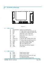
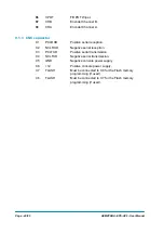
9.1.3 CNC
connector
C1
PCLRXD
Positive serial reception.
C2
NCLRXD
Negative serial reception.
C3
PCLTXD
Positive serial transmission.
C4
NCLTXD
Negative serial transmission.
C5
GND
Negative console power supply.
C6 +12
Positive console power supply.
C7
FLASH
Must be connected to C8 for the Flash memory
programming (if used).
C8
FLASH
Must be connected to C7 for the Flash memory
programming (if used).
Summary of Contents for EPS-AC0
Page 23: ...AEMZP0BA EPS AC0 User Manual Page 23 95 6 2 EPS AC0 Stepper Motor diagram Figure 6 2...
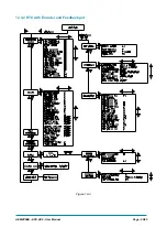
Page 24: ...Page 24 95 AEMZP0BA EPS AC0 User Manual 6 3 EPS AC0 Twin pot diagram Figure 6 3...
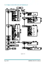
Page 55: ...AEMZP0BA EPS AC0 User Manual Page 55 95 12 3 2 RTC with Encoder and Feedback pot Figure 12 3...