


Page - 66/95
AEMZP0BA - EPS-AC0 - User Manual
1) SYSTEM
CONFIG
Level 0 to 6.
This setting is used to select the steer configuration (i.e. the open
or closed loop mode and the type of command sensors) in the following
combination list.
- LEVEL
0:
Stepper motor with feedback sensor.
This is an open loop
configuration. The stepper motor is used as a
tachogenerator to supply the wished steering motor speed.
The feedback sensor is not strictly necessary in open loop
configuration; in spite of that, this setting specifies the
feedback sensor is present and it will be used for the
automatic function (AUTC), maximum angle limitation,
detection of the locked motor and to perform the alignment at
the rest position.
The FEEDBACK DEVICE option (see 12.4.1.3) specifies
which kind of feedback sensor is adopted.
- LEVEL1:
Twin pot with feedback sensor.
This is a closed loop
configuration. The twin pot supplies the commanded position
for the steered wheel. The feedback sensor is mandatory to
close the loop with the commanded position. The twin pot is
a double potentiometer with complementary action (see
4.4.2).
The FEEDBACK DEVICE option (see 12.4.1.3) specifies
which kind of feedback sensor is adopted.
- LEVEL
2:
Via CAN demanded-speed with feedback sensor.
This is
an open loop configuration. A remote unit provides the
wished steering motor speed via CAN Bus. The feedback
sensor is not strictly necessary in open loop configuration; in
spite of that, this setting specifies the feedback sensor is
present and it will be used for the automatic function (AUTC),
maximum angle limitation, detection of the locked motor and
to perform the alignment at the rest position.
The FEEDBACK DEVICE option (see 12.4.1.3) specifies
which kind of feedback sensor is adopted.
- LEVEL
3:
Via CAN demanded-position with feedback sensor.
This
is a closed loop configuration. A remote unit provides the
commanded position for the steered wheel via CAN Bus.
The feedback sensor is mandatory to close the loop with the
commanded position.
The FEEDBACK DEVICE option (see 12.4.1.3) specifies
which kind of feedback sensor is adopted.
- LEVEL
4:
Stepper motor without feedback sensor.
This is an open
loop configuration. The stepper motor is used as a
tachogenerator to supply the wished steering motor speed.
As the feedback sensor is not strictly necessary in open loop
mode, it is possible to work without feedback sensor at all. In
spite of that, when the maximum angle limitation via
feedback sensors is enabled (option LIMIT DEVICE to ON
when FEEDBACK DEVICE is OPTION #1,2,3; 1
ST
ANGLE
COARSE and 2
ND
ANGLE COARSE less than level 9 when
FEEDBACK DEVICE is OPTION #4), the feedback sensor is
expected to perform the secondary functions of maximum
angle limitation, detection of the locked motor and to perform
the alignment at the rest position. When these conditions are
met, the FEEDBACK DEVICE option (see 12.4.1.3) specifies
which kind of feedback sensor is adopted for the secondary
Summary of Contents for EPS-AC0
Page 23: ...AEMZP0BA EPS AC0 User Manual Page 23 95 6 2 EPS AC0 Stepper Motor diagram Figure 6 2...
Page 24: ...Page 24 95 AEMZP0BA EPS AC0 User Manual 6 3 EPS AC0 Twin pot diagram Figure 6 3...
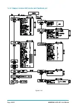
Page 55: ...AEMZP0BA EPS AC0 User Manual Page 55 95 12 3 2 RTC with Encoder and Feedback pot Figure 12 3...