


Page - 50/95
AEMZP0BA - EPS-AC0 - User Manual
Step3
Set the NO LOAD CURRENT adjustments to the current the motor drains
when lightened at the maximum flux (see 12.4.2.10).
Step4
Leave the handle steer in its straight position. Enter and Save the
adjustment ZERO SP POT (see 12.4.2.16). This operation is used to
automatically learn the twin pot voltage.
Step5
Set AUTO REQ TYPE in the set model menu to level 0 (no automatic
function).
Step6
Leave the handle steer in its straight position. Drive the truck and roll up and
down the adjustment SET STEER 0-POS until the truck is straight travelling.
Step7
Set 1ST ANGLE COARSE (and FINE) to get the steered wheel position
limited at +90 degrees when the SET POINT POT reading is maximum.
This is the direction where the FEEDBACK ENC reading is higher than 2.5
Vdc.
Step8
Set 2ND ANGLE COARSE (and FINE) to get the steered wheel position
limited at -90 degrees when the SET POINT POT reading is minimum. This
is the direction where the FEEDBACK ENC reading is lower than 2.5 Vdc.
Step9
Try to adjust the NUMBNESS parameter to get the steer less sensitive
when close to the straight ahead direction (see 12.4.4.17). (For every new
NUMBNESS value, repeat the above Step7 and Step8).
Step10
Try different settings for KP, POS. ACCURACY, LEAD FB REGULAT and
LAG FB REGULAT to avoid overshoot or damping during the pursuing
operation (see paragraph 12.4.4).
Step11
(CAN Bused system only). Set the Dynamic Numbness in closed loop
(steering sensitivity reduces when the truck speed increases). The
parameters to handle this function are AUX FUNCTION#2 and AUX
FUNCTION #3 (see 12.4.4.5-4).
Step12
(No CAN Bused system only). Connect a traction travel demand to CNA#1.
It can be a tiller switch (or a dead-man or a seat switch). This operation
supplies the information the truck is moving or not to stand-by the steer
when the truck is standing.
11.1.4 RTC & AUTC
When the AUTC is required, it is necessary to carry out all the Steps in paragraph
11.1.3 together with the following:
Step1
When the autocentering (AUTC) is required, it is necessary to contact a
Zapi technician to decide the physical and the superior protocol layers for
the AUTC demanding. (AUTC is a customized function that the eps-ac0
does not execute in its standard version).
One possible arrangement for the AUTC request could be a via CAN bus
demanded centering.
11.2 Quick set-up
This procedure shall be executed on every manufactured truck. It changes with the
configuration. We assume the default setting includes the correct value for SET
ENC AT 360 in a configuration with feedback enc and toggle switches. When a
configuration with the feedback pot is adopted, step 11 to step 15 in paragraph 10.3
are required too (acquisition of the limits).
11.2.1 Stepper Motor only
No set-up required on a truck working open loop (stepper motor) in manual mode
only.
Summary of Contents for EPS-AC0
Page 23: ...AEMZP0BA EPS AC0 User Manual Page 23 95 6 2 EPS AC0 Stepper Motor diagram Figure 6 2...
Page 24: ...Page 24 95 AEMZP0BA EPS AC0 User Manual 6 3 EPS AC0 Twin pot diagram Figure 6 3...
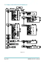
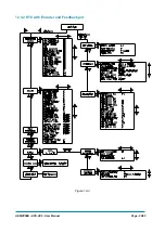
Page 55: ...AEMZP0BA EPS AC0 User Manual Page 55 95 12 3 2 RTC with Encoder and Feedback pot Figure 12 3...