


AEMZP0BA - EPS-AC0 - User Manual
Page - 47/95
Step1
Connect the AC motor phases in such a way the phase references U, V, W
on the steering motor correspond to the terminals references (U, V, W) on
the eps-ac0.
Step2
In the SET MODEL menu set the SYSTEM CONFIG setting to LEVEL 0 to
steer in open loop with a stepper motor in manual mode. Turn off and on the
key in order the setting is acquired.
Step3
Set the FEEDBACK DEVICE to OPTION #4 to specify your feedback
solution is the encoder with one or two toggle switches. Switch off the key
after the change.
Step4
Turn the special adjustment DEBUG OUTPUT to Level 11 to inhibit the
alarm POSITION ERROR and recycle the key.
Step4
Set option ENCODER CONTROL to OFF.
Step5
Connect the encoder. The encoder supply is between CNB#4 (5 Vdc) and
CNA#11 (GND): the two channels are CNB#8 (CHA) and CNB#7 (CHB).
Step6
Verify the reading ENC SPEED in the tester menu is consistent with the
reading FREQUENCY in the tester menu. Consistent means that ENC
SPEED and FREQUENCY must have the same sign and a close value. If
ENC SPEED has a wrong sign, swap CHA (CNB#8 with CHB (CNB#7). If
ENC SPEED is not close to FREQUENCY, the encoder resolution is wrong
and a different SW is needed (see 12.4.7.12 and 12.4.7.8).
Step7
If the motor runs well without glitches, it is possible to stays with ENCODER
CONTROL to OFF; otherwise, turn ENCODER CONTROL to ON.
Step8
Verify the steered wheel rotates in the correct direction according to the
hand wheel. If it isn’t, swap DL (CNA#9) with QL (CNA#8).
Step9
Set the LIMIT DEVICE option to OFF to avoid the maximum angle
limitations.
Step10
Detect the encoder counting corresponding to a steered wheel revolution.
To do that, turn the steered wheel some revolutions in CW direction and
read the ENC COUNT AT 360 in the tester menu. At every falling edge of
the CNA#3 toggle switch (SW1), this reading is updated. It corresponds to
the encoder counting for a complete revolution of the steered wheel. ENC
COUNT AT 360 shows real time the encoder counting between two
consecutive falling edges on the straight ahead toggle switch. The reading
is scaled in the range 0 to
±
5 V.
5 V corresponds to an encoder counting of 2
15
events.
-5 V corresponds to an encoder counting of -2
15
events.
To be sure the shown value is correct, turn the steered wheel some
revolutions in the opposite direction. I expect the reading ENC COUNT AT
360 gets the same value but with opposite sign.
Step11
Enter and save the adjustment SET ENC AT 360. The absolute value in the
reading ENC COUNT AT 360 will be recorded on SET ENC AT 360.
Step12
Recycle the key and turn the steered wheel to get the WHEEL ANGLE
reading in the tester menu close to 0 degrees.
Step13
Check the orientation of the steered wheel in the position having WHEEL
ANGLE close to 0. If the steered wheel has not the wished orientation
change AUX FUNCTION 11. If AUX FUNCTION 11 is set to Level 5, it is
necessary to change to Level 4 or vice versa. If AUX FUNCTION 11 is set
to Level 2, it is necessary to change to Level 3 or vice versa.
Step14
Recycle the key. Now, when WHEEL ANGLE is null, the steered wheel
must be oriented in the wished direction.
Step15
Turn the steered wheel to have the reading WHEEL ANGLE close to +45
degrees (first sector). Read the ENDSTROKE CW and ENDSTROKE ACW
in the tester menu. Set AUX FUNCTION 11 to the proper level as specified
below:
ENDSTROKE CW=OFF and ENDSTROKE ACW=OFF:
Level 2
Summary of Contents for EPS-AC0
Page 23: ...AEMZP0BA EPS AC0 User Manual Page 23 95 6 2 EPS AC0 Stepper Motor diagram Figure 6 2...
Page 24: ...Page 24 95 AEMZP0BA EPS AC0 User Manual 6 3 EPS AC0 Twin pot diagram Figure 6 3...
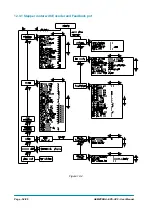
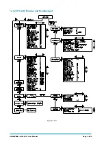
Page 55: ...AEMZP0BA EPS AC0 User Manual Page 55 95 12 3 2 RTC with Encoder and Feedback pot Figure 12 3...