


Page - 64/95
AEMZP0BA - EPS-AC0 - User Manual
by rolling the DEBUG OUTPUT to 0 (see 12.4.6.4).
12) AUX VOLTAGE #2
(Factory adjusted). This is the self-acquired offset value of the stepper motor
line connected to CNA#8. The default value is 2.500 mV and can be re-acquired
by rolling the DEBUG OUTPUT to 0 (see 12.4.6.4).
13) SET MIN FB POT
(Versions with FB POT only).
This adjustment is used to self-acquire (see 10.3
and 10.4) the feedback pot value and the encoder counting corresponds to the
limiting position having the FEEDBACK POT reading lower than 2.5V (typically -
90 degrees). If the option LIMIT DEVICE is set On, the steered wheel angle will
be limited when the FEEDBACK POT reading is lower than SET MIN FB POT
value.
14) SET MAX FB POT
(Versions with FB POT only).
This adjustment is used to self-acquire (see 10.3
and 10.4) the feedback pot value and the encoder counting corresponds to the
limiting position having the FEEDBACK POT reading higher than 2.5 V (typically
+90 degrees). If the option LIMIT DEVICE is set On, the steered wheel angle
will be limited when the FEEDBACK POT reading is higher than SET MAX FB
POT value.
15) SET ENC AT 360
(Versions with FEEDBACK DEVICE to OPTION #4 only).
This adjustment is
used to self-acquire (see 10.4) the encoder counting corresponding to a
complete steered wheel revolution. It is used in the arrangements using the FB
ENC and Toggle switches to properly scale the encoder counting with the
steered wheel angle (WHEEL ANGLE).
16) ZERO SP POT
(RTC version only). This adjustment is used to self-acquire (see 11.1.3 and
11.2.3) the voltages on the twin potentiometers when the steer handle is
released in its straight ahead position. Just push the enter button with a
released steer handle to record the new ZERO SP POT value.
17) SET STEER 0-POS
Although ZERO SP POT was acquired, it is possible the steer handle is
released but the steered wheel is not straight-ahead yet. This offset can be
compensated through this adjustment. It must be set to the FEEDBACK ENC
value corresponding to a perfectly straight-ahead steered wheel. This setting is
used for manual mode RTC and AUTC.
SET STEER 0-POS may be rolled up or down in 5 mV steps.
18) SET FBPOT AT SW1
(Versions with FEEDBACK DEVICE to OPTION #3 only). Reading READ FBPT
AT SW1 provides the FB POT value at the initial matching with the falling edge
on the straight ahead switch (SW1). By entering adjustment SET FBPOT AT
SW1, its value changes to the value of reading READ FBPOT AT SW1 (i.e. the
READ FBPO AT SW1 is recorded on SET FBPOT AT SW1). In normal
condition, reading READ FBPT AT SW1 is expected to reply the SET FBPOT
AT SW1 value. When a displacement exists between these two values, a
POSITION ERROR alarm may occur (see 14.1.3.5).
Summary of Contents for EPS-AC0
Page 23: ...AEMZP0BA EPS AC0 User Manual Page 23 95 6 2 EPS AC0 Stepper Motor diagram Figure 6 2...
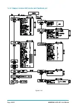
Page 24: ...Page 24 95 AEMZP0BA EPS AC0 User Manual 6 3 EPS AC0 Twin pot diagram Figure 6 3...
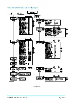
Page 55: ...AEMZP0BA EPS AC0 User Manual Page 55 95 12 3 2 RTC with Encoder and Feedback pot Figure 12 3...