background image

VS-616PS5 Programming Manual

51


Setting Range:

0 to 50%

Factory Default:

10%

This sets the excessive speed deviation detection level as a percentage of maximum 
output speed 

(E1-06)

. Used in conjunction with parameter

 F1-11

 to sense a speed 

deviation condition.

Setting Range:

0.0 to 10.0s

Factory Default:

0.5s

This parameter sets the elapsed time for which a speed deviation condition must 
exist, before a fault (or alarm) is generated. 

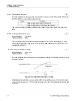
A fault (or alarm) signal is output after the deviation between speed reference and the 
actual motor speed exceeds the set value of 

F1-10

 and after the time set to 

F1-11


elapses.  The stopping method is set with 

F1-04

.  Also, detection is not activated 

while accelerating/decelerating or during torque control.

Setting Range:

0.0 to 10.0s

Factory Default:

3.0s

This sets the time for which a PG open condition must exist, before a fault (or alarm) 
is generated.

The stopping method, when a “PGO” condition is detected, is selected by param-
eter 

F1-02

.

F1-10 PG Deviation Detection Level

A

F1-11 PG Deviation Detection Time

A

F1-13

PG Open Detection Delay Time

A

Figure 30  Overspeed Detection Timing Diagram

Speed Reference

OFF

ON

Motor Speed

F1-10

Speed Deviation 

Fault Signal

F1-11

OFF

Section F: Option Parameters

F1 PG Option Set-up

Summary of Contents for VS-616PS5 Series

Page 1: ...VS 616PS5 Series Programming Manual Brushless Motor Drive ...

Page 2: ...2 VS 616PS5 Programming Manual ...

Page 3: ...l controls should be designed to detect faults dynamically and fail safely under all circumstances All products designed to incorporate a component part manufactured by YASKAWA must be supplied to the end user with appropriate warnings and instructions as to that part s safe use and operation Any warnings provided by YASKAWA must be promptly provided to the end user YASKAWA offers an express warra...

Page 4: ...igh withstand voltage tester on the VS 616PS5 Higher volt ages can damage the semiconductors used in the inverter Do not connect or disconnect the operator or a computer while the VS 616PS5 is running FAILURE TO OBSERVE THE WARNINGS AND PRECAUTIONS IN THIS MANUAL CAN EXPOSE THE USER TO HIGH VOLTAGES RESULTING IN DAMAGE TO EQUIPMENT SERIOUS PERSONAL INJURY OR EVEN DEATH POWER SUPPLY LIMITATIONS The...

Page 5: ...rrier Frequency 31 D REFERENCE PARAMETERS 35 D1 Preset References 35 D2 Reference Limits 37 D3 Jump Frequencies 38 D4 Hold Reference Memory 39 D5 Torque Control 40 E MOTOR PARAMETERS 44 E1 Motor Constant 44 F OPTION PARAMETERS 49 F1 PG Option Set up 49 F2 AI 14 Set up 52 F3 DI 08 DI 16H Set up 53 F4 AO 08 AO 12 Set up 44 F5 DO 02 Set up 56 F6 DO 08 Set up 57 F9 CP 916 Set up 59 H CONTROL CIRCUIT T...

Page 6: ...gramming Manual Section Description Page L8 Hardware Protection 93 O OPERATOR PARAMETERS 95 O1 Monitor Selection 95 O2 Key Selection 97 T TUNING PARAMETERS 100 T1 Auto tuning 100 Appendix VS 616PS5 PARAMETER LIST 101 ...

Page 7: ...anufactured worldwide Some of Yaskawa s proprietary features of the VS 616PS5 inverter include torque control automatic tuning to the motor characteristics UL recognized electronic thermal motor over load energy saving operation PID loop control and low noise operation Also available is a digital operator for simple programming The design team has used the latest in micropro cessor technology to p...

Page 8: ...eed 01 04 D4 Hold Reference Memory 01 D5 Torque Control 01 06 E1 Motor Constant 01 13 17 15 16 F1 PG Option Set up 01 05 02 04 08 11 13 F2 AI 14 Set up 01 F3 DI 08 16 Set up 01 F4 AO 08 12 Set up 01 06 F5 DO 02 Set up 01 02 F6 DO 08 Set up 01 F8 Speed Feedback Selection 01 02 F9 CP 916 Set up 01 06 H1 Digital Inputs 01 06 H2 Digital Outputs 01 03 H3 Analog Inputs 01 03 04 12 H4 Analog Outputs 01 0...

Page 9: ...evel factory default For maintenance level programming 3 Basic Level For basic programming in most applications 4 Advanced Level For advanced programming in special applications A1 03 Operator Status Q Setting Description 0 No Initialization factory default 2220 2 Wire Initialization terminal 1 becomes FWD run command and terminal 2 becomes REV run command All other parameters are reset to their o...

Page 10: ... Method is reset to remote operation when power is cycled Setting Range 0 to 3 Factory Default 0 This function selects the stopping method suitable for the application B1 01 Frequency Reference Selection Q B1 02 Operation Method Selection Q Setting Description 0 Run by digital operator reference 1 Run by external terminal reference factory default 2 Run by serial communication 3 Option card run by...

Page 11: ...without braking resistor approximately 5 of motor rated torque with braking option approximately 150 of motor rated torque Coast to Stop B1 03 1 Upon removal of the FWD REV run command the motor starts to coast Upon re applying the run command operation will resume after the minimum baseblock time L2 03 elapses Coast to Stop with Timer 1 B1 03 3 should be used to prohibit the inverter from startin...

Page 12: ...terminal or the digital operator This setting is used in applications where a reverse run command is undesirable Select an operation mode to be used when the speed reference analog input drops below the minimum speed setting El 08 B1 04 Reverse Operation Enable Disable B Setting Description 0 Reverse run is enabled factory default 1 Reverse run is disabled B1 05 Operation Selection at Zero Speed A...

Page 13: ...Zero speed operation internal speed reference is set to 0 B1 06 LOCAL REMOTE Run Select A Selection Description 0 Operation is disabled if the external run command is applied prior to switching from local to remote The run command must be removed and re applied to start operation 1 Operation is enabled if the external run command is applied prior to switching from local to remote factory default S...

Page 14: ...0 5 Sets the speed at which the inverter baseblocks upon deceleration 20 equals 20 of the maximum speed setting as entered in parameter E1 06 The initial value is 0 5 The units can be changed by O1 03 B2 01 Zero speed Level Baseblock level B Section B Application Parameters B2 Servo Speed Level ...

Page 15: ...n is completed the PG Orientation feature is performed Setting Range 0 to 150 Factory Default 50 The current level during initial magnetic pull in is set in units of 1 A setting of 100 generates Motor rated current E1 04 Increasing this value increases the motor torque during the pull in process Setting Range 0 0 to 5 0s Factory Default 1 0s Sets the rate at which the current is increased during t...

Page 16: ...ng time is set in units of 0 1s The current vs time plot during the magnetic pull in process is as follows B3 05 Magnetic Pull in Time A Operation Status B3 02 Adjustment B3 04 Adjustment B3 05Adjustment Slow Start Decrease set value Decrease set value Insufficient torque and STO is output Increase set value Current Value 0 1 2 Time B3 04 B3 05 B3 02 Section B Application Parameters B3 Magnetic Pu...

Page 17: ...s the ON delay time in units of 0 1 second The multi function input must be closed for longer than the ON delay timer for the multi function output to close Setting Range 0 0 to 300 0s Factory Default 0 0s Sets the OFF delay time in units of 0 1 second The multi function input must be open longer than the OFF delay timer for the multi function output to open B4 01 On delay Timer A B4 02 Off delay ...

Page 18: ...nt and detected value feedback setpoint as follows Detected Value Feedback Set the PID feedback value with the control circuit terminal 16 voltage signal 0 to 10V 10 to 10V or multi step speed parameters H1 03 to H1 06 Control circuit terminal 16 voltage signal Set reference selection B1 01 to 1 and set H3 05 B Multi step speed parameters via multifunction inputs H1 01 to H1 06 Set reference selec...

Page 19: ... a multi function contact input signal By setting any of parameters H1 01 to H1 06 to 19 and by closing the contact during running PID control is disabled and the intended value sig nal itself is used as a frequency reference signal Setting Range 0 00 to 25 00 Factory Default 1 00 The proportional gain is the value by which the deviation signal is multiplied to gener ate a new frequency reference ...

Page 20: ...nge 0 00 to 10 00s Factory Default 0 00s The derivative calculation attempts to control the remaining overshoot left over after the proportion and integral calculations If the system is approaching the intended value very rapidly the derivative control produces a strong braking action to prevent overshoot If the system is already stable with very little deviation change derivative control has very...

Page 21: ...imum values for most applications and hence do not need to be changed When tuning a system first increase the proportional gain until oscillations occur Then reduce the proportional gain slightly until the oscillations stop Next reduce the integral time slowly until oscillations begin Then increase the integral time slowly so that the oscillations cease Test the system under all conditions observe...

Page 22: ...Range 0 00 to 100 00 Factory Default 0 00 Sets the dwell frequency reference during acceleration in units of 0 01 Setting Range 0 0 to 10 0s Factory Default 0 0s Sets the amount of time that the frequency reference dwells during acceleration in units of 0 1s Setting Range 0 00 to 100 00 Factory Default 0 00 Sets the dwell frequency reference during deceleration in units of 0 01 Setting Range 0 0 t...

Page 23: ...setting of 100 allows the speed to drop 100 of the maximum speed value when the torque is 100 Droop response time is set with parameter B7 02 Setting Range 0 00 to 1 00s Factory Default 0 10s When B7 02 is decreased drooping response becomes quicker but the motor hunts more easily B7 01 Droop Capacity A B7 02 Droop Delay Time A B7 01 100 Droop amount x 100 Torque Load Motor Speed B7 02 63 Droop Am...

Page 24: ...e accel decel time selection commands terminals 3 to 8 C1 01 Acceleration Time 1 Q C1 02 Deceleration Time 1 Q C1 03 Acceleration Time 2 B C1 04 Deceleration Time 2 B C1 05 Acceleration Time 3 A C1 06 Deceleration Time 3 A C1 07 Acceleration Time 4 A C1 08 Deceleration Time 4 A Output Frequency Accel Time 1 C1 01 Decel Time 1 C1 02 Accel Time 2 C1 03 Decel Time 2 Decel Time 1 Time FWD REV Run Comm...

Page 25: ... frequency C1 11 Use accel decel times set in parameters C1 07 and C1 08 when output frequency C1 11 Multi function contact inputs which are set for accel decel selection have priority over Accel decel Time Selection 1 Multi function Input Setting 7 Accel decel Time Selection 2 Multi function Input Setting 1A Accel Time Decel Time Open or not set Open or not set C1 01 C1 02 Closed Open or not set ...

Page 26: ...gramming Manual the automatic change of accel decel Output Frequency C1 07 Accel Decel Switching Level C1 01 C1 02 C1 08 C1 11 Figure 14 Accel Decel Switching Level Adjustment Section C Tuning Parameters C1 Accel Decel ...

Page 27: ... the hall sensor or encoder feedback devices This value is used to control the commutation to insure optimum performance This value is automatically set when performing PG origin auto tuning Do not change after setting This value is not initialized at initialization C2 13 PG Origin Pulse Compensation Value Q Section C Tuning Parameters C2 PG Origin Pulse Compensation ...

Page 28: ...ntrol C3 05 Voltage Limit Control Selection A Set Value Description 0 Voltage limitation control is not performed fac tory default 1 Voltage limitation control is performed limits the output voltage to 230 460 by reducing the d axis current level Section C Tuning Parameters C3 Voltage Limit Control ...

Page 29: ... load Response increases as the integral time is decreased However the load may become unstable if the ASR integral time is set too low Setting Range 0 00 to 300 00 Factory Default 5 00 The ASR proportional gain 2 is an additional proportional gain adjustment that can be enabled by a multi function contact input H1 XX 77 C5 01 ASR Proportional Gain 1 B C5 02 ASR Integral Time 1 B C5 03 ASR Proport...

Page 30: ...5 02 are achieved When C5 06 is set to any set ting other than 0 both sets of proportional and integral values are used See Figure 22 Notes 1 When C5 06 0 proportional gain 1 C5 01 and integral time 1 C5 02 are selected Setting Range 0 00 to 300 00 Factory Default 5 00 This parameter sets the ASR P gain applied at magnetic pole pull in It is set to a unit of 0 01 C5 04 ASR Integral Time 2 B C5 05 ...

Page 31: ...ault values current derating is necessary Factory Settings C6 02 Carrier Frequency Upper Limit A 230 Volt Models Model Number Carrier Frequency PS5U20P4 8kHz PS5U20P7 PS5U21P5 PS5U22P2 PS5U23P7 PS5U25P5 PS5U27P5 PS5U2011 PS5U2015 460 Volt Models Model Number Carrier Frequency PS5U40P4 8kHz PS5U40P7 PS5U41P5 PS5U42P2 PS5U43P7 PS5U45P5 PS5U47P5 PS5U4011 PS5U4015 PS5U4018 PS5U4022 PS5U4030 PS5U4037 4...

Page 32: ...S 616PS5 Programming Manual PS5U4185 2kHz PS5U4220 PS5U4300 460 Volt Models Model Number Carrier Frequency Section C Tuning Parameters C6 Carrier Frequency Speed Reference C6 14 C6 13 1 100 Pulse Reference ...

Page 33: ... Train reference mode Setting Range 0 1000 Factory Default 0 Sets the numerator portion of the pulse reference multiplication block Used when B1 02 6 Pulse Train reference mode C6 13 Pulse Reference Ratio Denominator Value A C6 14 Pulse Reference Ratio Numerator Value A Speed Reference C6 14 C6 13 1 100 Pulse Reference Section C Tuning Parameters C6 Carrier Frequency ...

Page 34: ...eleration Start A C7 02 S Curve Time at Acceleration End A C7 03 S Curve Time at Deceleration Start A C7 04 S Curve Time at Deceleration End A Output Frequency Frequency Reference Output Frequency S curve Characteristic Time Time Tsc Figure 15 S curve Characteristic Timing Diagram FWD Run Command REV Run Command Output Frequency C7 02 C7 03 C7 01 C7 04 DC Injection Braking Time at Stop B2 04 Figur...

Page 35: ...6 6 Selecting the jog frequency reference via a multifunction input selects the jog frequency reference only A separate run command also needs to be applied to start the unit D1 01 Preset Reference 1 Q D1 02 Preset Reference 2 Q D1 03 Preset Reference 3 Q D1 04 Preset Reference 4 Q D1 05 Preset Reference 5 B D1 06 Preset Reference 6 B D1 07 Preset Reference 7 B D1 08 Preset Reference 8 B Terminal ...

Page 36: ...Selection for more details Multi step Speed Ref 1 Frequency Reference FWD REV Run Stop Terminal 5 Multi step Speed Ref 2 Terminal 6 D1 04 40 0Hz D1 01 10 0Hz D1 02 20 0Hz D1 03 30 0Hz ON ON ON ON Figure 24 Multi step Speed Operation Timing Diagram Multi step Speed Ref 3 Terminal 7 Jog Ref Terminal 8 ON ON ON ON ON D1 05 45 0Hz D1 06 50 0Hz D1 07 55 0Hz D1 08 60 0Hz D1 09 6 0Hz Time Section D Refer...

Page 37: ...centage of the maximum output speed E1 06 When a run command is input and the speed reference is less than the lower limit operation continues at the speed reference lower limit However when the lower limit is set to less than the minimum output speed E1 08 operation dis continues D2 01 Speed Reference Upper Limit B D2 02 Speed Reference Lower Limit B D2 01 Set Frequency Reference Internal Speed R...

Page 38: ...rate without resonant vibrations caused by some machine systems They are also used for dead band controls Setting the value to 0 0 disables each function D3 01 Jump Speed Reference 1 A D3 02 Jump Speed Reference 2 A D3 03 Jump Speed Reference 3 A D3 04 Jump Speed Reference Bandwidth A D3 02 D3 01 D3 04 D3 04 Set Frequency Reference Figure 26 Jump Frequencies D3 03 D3 04 Output Frequency Section D ...

Page 39: ...nputs for more information D4 01 Reference Memory Selection Up Down or Accel Decel Hold Feature A Setting Description 0 Reference memorization during Up Down or Accel Decel Hold operation not retained If a stop command is given or if power is removed the frequency reference is reset to 0Hz If the inverter is decelerating when the run command is restored operation resumes at the frequency reference...

Page 40: ...Range 120 Factory Default 0 Sets the speed limit value in the torque control mode as a percentage of the maxi mum output frequency Used when D5 03 2 Setting Range 0 to 120 Factory Default 5 Sets the speed limit bias value in the torque control mode as a percentage of the maximum output frequency See Torque Control Operation description on following page D5 01 Torque Control Selection A Setting Des...

Page 41: ...peed limit when speed limit selection D5 03 is set to 2 the set value of D5 04 becomes the speed limit 2 When terminal 14 function selection is set to torque compensation H3 09 14 the terminal l4 set value can be used as the torque compensation value When torque reference 0 and speed limit 0 winder application sequence the fol lowing sequence is activated When 1 speed limit bias D5 05 motor speed ...

Page 42: ...nfiguration Direction of Motor Rotation Forward Reverse Forward Reverse Refer ence Polarity Torque Refer ence TREF Speed Limit NLIM Torque Profile Terminal No Parameter No Setting Description 8 H1 06 71 Speed torque control selection 13 B1 01 D5 03 1 1 Frequency reference selection terminals 13 14 Speed limit selection terminals 13 14 16 H3 05 13 Torque reference M Motor Line Direction T N M Motor...

Page 43: ...d limit value D5 04 when D5 03 2 regardless of the frequency ref erence selection B1 01 setting During torque control the terminal 16 analog input value becomes the torque reference ƒ By giving a stop command during torque control operation changes to speed con trol automatically and the motor decelerates to stop The torque limit during deceler ation to stop becomes the values set in the torque li...

Page 44: ...ting E1 02 to any setting other than 1000 be sure to set E1 17 to the proper con nection setting first Then set E1 03 to the proper motor winding type When set to 1000 manual entry of parameter E1 03 E1 13 is required Do not change the value after it has been set as the motor parameters will be modi fied Setting Range 0 0 to 255 0V 0 510 0 V Factory Default 230 0 460 0 Sets the motor rated voltage...

Page 45: ...6000rpm Factory Default 1 E1 02 1000 Set the maximum motor speed with this parameter in units of 1rpm Avoid the con stant horsepower range due to lack of field weakening control in the brushless DC machine Setting Range 0 to 6000rpm Factory Default 1 E1 02 1000 Base motor speed is set in units of 1rpm Setting Range 0 to 6000rpm Factory Default 30 E1 02 1000 The minimum motor operating speed is set...

Page 46: ...ange 20 0 to 500 0 V 1000 RPM Factory Default 0 0 E1 02 1000 This parameter sets the induced voltage RMS value for the motor in units of 0 1V 1000 RPM Enter the induced voltage generated at 1000 RPM motor speed Make sure the induced voltage at the maximum speed E1 06 does not exceed the voltage rating of the inverter Do not change the value after it has been set Setting Range 0 0 to 10 0 Factory D...

Page 47: ...ted voltage E1 03 V Setting Range 0 to 3 Factory Default 0 Sets the winding connection configuration for the connected motor Used only when using the winding data look up tables E1 02 is not equal to 1000 see Installation Quick Start Manual Set E1 17 to the proper configuration first then set E1 02 to the proper winding code This parameter is not used if E1 02 1000 0 1 Connection E1 16 Motor Feede...

Page 48: ...48 VS 616PS5 Programming Manual 1 2 Connection 2 1Y Connection 3 2Y Connection T1 T2 T3 T1 T2 T3 T1 T2 T3 Section E Motor Parameters E1 V f Pattern ...

Page 49: ... the stopping method when excessive speed deviation is detected F1 01 PG Pulses per Revolution Q F1 02 PG Disconnection Detection Stopping Method B Setting Description 0 Ramp to stop according to C1 02 Declaration time 1 1 Coast to stop factory default 2 Fast stop according to C1 09 3 Alarm flashes operation continues F1 03 Overspeed Detection Stopping Method B Setting Description 0 Ramp to stop a...

Page 50: ...tory Default 0 0s Sets the elapsed time from when an overspeed condition is detected to when a fault or alarm occurs A fault signal is output to stop operation after the absolute value of the motor speed exceeds the set value of F1 08 for the time set to F1 09 The stopping method is set by F1 03 F1 05 PG Rotation Selection Q Setting Description 0 HS5 leads HS4 channel B leads A in FWD direction 1 ...

Page 51: ...tor speed exceeds the set value of F1 10 and after the time set to F1 11 elapses The stopping method is set with F1 04 Also detection is not activated while accelerating decelerating or during torque control Setting Range 0 0 to 10 0s Factory Default 3 0s This sets the time for which a PG open condition must exist before a fault or alarm is generated The stopping method when a PGO condition is det...

Page 52: ...ulti function contact input H1 XX 2 is disabled when using the AI 14B option F2 01 AI 14B Function Selection A Setting Function CH1 TC1 to TC4 CH2 TC2 to TC4 CH3 TC3 to TC4 0 3 channel individual input factory default Substitute for terminals 13 17 Substitute for terminals 14 17 Substitute for terminals 16 17 1 3 channel additional input Sum of CH1 to CH3 input values is used as the speed referenc...

Page 53: ...DI 08 and DI 16H options F3 01 Digital Input Option A Setting Frequency Reference Setting Mode 0 BCD 1 unit factory default 1 BCD 0 1 unit 2 BCD 0 01 unit 3 Not used 4 Not used 5 Not used 6 Not used 7 Binary DI 08 255 100 DI 16H 12 bit selection 4096 100 DI 16H 16 bit selection 30000 100 Section F Option Parameters F3 DI 08 DI 16H Set up ...

Page 54: ...input voltage 16 External terminal 14 input voltage 17 External terminal 16 input voltage 18 Motor secondary current Iq 19 Motor excitation current Id 20 Primary frequency after SFS 21 Speed controller ASR input 22 Speed controller ASR output 27 qAxis current control reference 28 dAxis current control reference 29 Voltage limit control output 30 qAxis current control output 31 dAxis current contro...

Page 55: ... channel 2 of the AO 08 and AO 12 options Select from the table included in parameter F4 01 Setting Range 300 0 Factory Default 1 0 This parameter sets the channel 2 output gain for the analog output monitors To determine the output level multiply the monitor output level by the gain value set in this parameter F4 05 Setting Range 109 2 Factory Default 0 0 Sets the channel 2 output bias for the an...

Page 56: ...run 1 factory default 12 Timer output 1 Zero speed 13 Agree 2 2 Sref Sout agree 1 14 Agree 2 3 Sref Sset agree 1 15 Speed detection 3 4 Speed detection 1 16 Speed detection 4 5 Speed detection 2 17 Torque detection 1 N C 6 Inverter ready 18 Torque detection 2 N O 7 DC bus undervoltage 19 Torque detection 2 N C 8 Baseblock 1 1A Reverse direction 9 Option reference 1B Baseblock 2 A Remote operation ...

Page 57: ...verter overheat OH1 TD1 TD2 During zero speed detection TD3 TD4 During speed agree 1 binary output TD5 TD11 Binary output TD6 TD11 TD7 TD11 TD8 TD11 TD9 TD11 During zero speed detection TD10 TD11 During speed agree TD1 TD2 During run TD3 TD4 Minor fault TD8 TD11 bit 3 TD7 TD11 bit 2 TD6 TD11 bit 1 TD5 TD11 bit 0 Description 0 0 0 0 No fault 0 0 0 1 Overcurrent SC OC GF 0 0 1 0 Overvoltage OV 0 0 1...

Page 58: ...le speed reference signal however the inverter response to a rapid change in reference may be slower A setting of 0 or 1 means no moving average will be used and the pulse train ref erence will be updated every scan F8 01 Speed Feedback Detection Method Q Setting Description 0 Speed feedback comes from channels A B on PG P2 option 1 Speed feedback comes from channels HS4 HS5 input on PG P2 option ...

Page 59: ...F9 01 External Fault Input Level from Communication Option A Set Value Description 0 Detection by N O when closed the inverter will trip factory default 1 Detection by N C when open the inverter will trip F9 02 External Fault Detection Selection from Communication Option A Set Value Description 0 The fault will always be detected even when the drive is stopped factory default 1 The fault will be d...

Page 60: ...P 916 commu nication options The fault will occur after initial communication has been estab lished and when the connection has been interrupted F9 05 Torque Reference Selection from Communication Option A Setting Description 0 Torque reference by analog input 1 Torque reference by Communication options factory default F9 06 Operation at Bus Error Detection A Setting Description 0 Ramp to stop acc...

Page 61: ...nction Input Terminal 7 Selection B H1 06 Multi function Input Terminal 8 Selection B Setting Function Reference Page 0 3 Wire Control 62 1 Local Remote Selection 62 2 Option Inverter Selection 62 3 Multi Step Ref 1 factory default H1 03 35 4 Multi Step Ref 2 factory default H1 04 35 5 Multi Step Reference 3 35 6 Jog Speed Ref factory default H1 05 35 7 Multi Accel Decel 1 24 8 External Baseblock ...

Page 62: ...en the contact input is closed External base block operation differs as described below depending on the run command input status Inputting an external baseblock signal while the inverter is running causes a BB indication on the digital operator display and the inverter output is shut OFF After removing the external baseblock command operation restarts at the previ ously referenced speed Inputting...

Page 63: ...al heat sensor for indication of device over temperature To close an output contact under this condition set a multi function contact output H2 XX to 20 Multi function Analog Input Enable Disable setting C This setting allows terminal 16 multi function analog input to be enabled accepted or disabled disregarded via a digital input Open Terminal 16 command is not accepted Closed Terminal 16 command...

Page 64: ...n after the power supply turns OFF When D4 01 0 the output frequency is not stored 5 If the jog frequency reference is input during Up Down operation the jog fre quency reference has priority Forward and Reverse JOG commands settings Fwd Jog 12 Rev Jog 13 Enables forward and reverse run jog frequency commands UP command Closed Open Open Closed DOWN command Open Closed Open Closed Operation Status ...

Page 65: ...If the contact input closes for 100ms or longer the analog speed reference is sampled once after which the analog speed reference is held Note t1 t3 Each reference is held for 100ms or longer t2 Reference is held for less than 100ms generating no frequency sampling Terminal 13 14 Selection setting 1F Open Terminal 13 is used for the master speed reference Closed Terminal 14 is used for the master ...

Page 66: ... the external fault function according to the following tree External Fault Selection Setting Result Input Level Selection Detection Method External Fault Action N O N C Always During Run Ramp to Stop Coast to Stop Fast stop Alarm Only 20 24 28 2C 22 26 2A 2E 21 25 29 2D 23 27 2B 2F H1 XX 24 Depress the Data Enter key Input Level Selection Detection Method External Fault Action N O Contact N C Con...

Page 67: ...factory default H2 02 68 2 Speed Agree 1 factory default H2 03 68 3 Desired Speed Agree 1 68 4 Speed Detection 1 69 5 Speed Detection 2 69 6 Inverter Ready 69 7 DC Bus Undervoltage 69 8 Baseblock 1 N O 69 9 Speed Reference Selection 69 A Run Command Selection 69 B Overtorque Detection 1 N O 70 C Loss of Speed Reference 70 D Dynamic Braking Resistor DB Overheat 70 E Fault 70 F Not used 10 Alarm Min...

Page 68: ...inus the speed agree detection width L4 02 This works in both forward and reverse operation Desired Speed Agree 1 setting 3 Closes whenever the output Speed agrees with the Speed Agree Detection Level L4 01 plus or minus the Speed Agree Detection Width L4 02 This works in both forward and reverse operation Detection Width 1 L4 02 Output Speed Speed Agree 1 Signal ON Speed Reference Figure 37 Speed...

Page 69: ... faults or alarms DC Bus Undervoltage setting 7 Closes when the main circuit DC bus voltage or control circuit power supply is drops below the trip level or when the main soft charge contactor MC is OPEN Baseblock 1 N O setting 8 Closes when the inverter output shuts OFF Speed Reference Selection setting 9 Open when the speed reference is entered from the control circuit terminals or option Closes...

Page 70: ... Overheat setting D Closes during braking resistor overheating or a braking transistor fault Fault setting E Closes when a fault occurs except CPF00 and CPF01 Alarm setting 10 Closes while an alarm is displayed Fault Reset setting 11 Closes while a fault is being reset Timer Output setting 12 Closes when a timer contact input closes after On delay time elapses Opens when a timer contact input open...

Page 71: ...e output Speed is at or above the Speed Agree Detection Level L4 03 During deceleration from above the detection level the output Speed decreases through the Detection Bandwidth L4 04 before the contact opens again Choose forward or reverse operation in L4 03 Choose forward or reverse operation in L4 03 Detection Width 1 L4 04 Output Speed Speed Agree 2 Signal ON Speed Reference Figure 42 Speed Ag...

Page 72: ... Opens when the inverter output shuts OFF Monitoring Regenerating Mode setting 1D Closes during regenerative operation Automatic Restart setting 1E Closes during automatic restart operation OL1 Pre alarm setting 1F Closes when the motor calculated electronic thermal overload value increases to 90 of the internal fault detection level OH Pre alarm setting 20 Closes when the heatsink temperature exc...

Page 73: ...he Speed Limit Level as determined by parameter setting D5 03 is reached during torque control The speed limit is set by D5 04 or the analog input During Run 2 setting 37 Closes during running does not close during baseblock injection braking or initial excitation Section H Control Circuit Terminal Parameters H2 Digital Outputs ...

Page 74: ...age is 10V Setting Range 100 0 Factory Default 0 0 Sets the terminal 13 input bias level when the reference voltage is 0V Selects the type of voltage signal input at terminal 16 The resolution of terminal 16 is 11 bit plus a sign bit H3 01 Terminal 13 Signal Selection B Setting Description 0 0 to 10V input factory default 1 10 to 10V input H3 02 Terminal 13 Reference Gain B H3 03 Terminal 13 Refer...

Page 75: ...ive Torque Limit 100 10V 13 Torque Reference 100 10V 14 Torque Compensation 100 10V 15 Forward Reverse Torque Limit 100 10V 1F Not Used Torque Compensation setting 14 100 10V 10V 100 0 100 10V 10V 0 100 10V 10V 0 100 10V 100 0 Auxiliary Speed Reference setting 0 Speed Gain setting 1 Speed Bias setting 2 Overtorque Level setting 7 Reference Lower Limit setting 9 Jump Speed setting A PID Feedback se...

Page 76: ...control printed circuit board J1 is located on the bottom left hand corner of the control board directly behind terminal 13 Selects the multi function analog input function for terminal 14 see Terminal 16 Multi function Selection for details Setting Range 0 0 to 1000 0 Factory Default 100 0 Sets the terminal 14 input gain level when the reference current is 20mA see Figure 46 H3 06 Terminal 16 Ref...

Page 77: ...g Range 0 00 to 2 00s Factory Default 0 00s Sets up a filter time constant for terminals 13 14 and 16 This filter can be used to filter a noisy or fluctuating analog signal The same filter time applies to all 3 analog signals H3 11 Terminal 14 Reference Bias A H3 12 Analog Input Filter Time Constant A Section H Control Circuit Terminal Parameters H3 Analog Inputs ...

Page 78: ...n 1 Speed reference 2 Output Speed factory default 3 Inverter output current 5 Motor speed 6 Output voltage 7 DC bus voltage 8 Output power 9 Torque reference internal 15 External terminal 13 input voltage 16 External terminal 14 input voltage 17 External terminal 16 input voltage 18 Motor secondary current Iq 19 Motor excitation current Id 20 Primary Speed after SFS 21 Speed controller ASR input ...

Page 79: ... by the gain value set in H4 05 see Figure 48 Setting Range 109 2 Factory Default 0 0 Sets the terminal 23 output bias for the analog output monitors To obtain the output level multiply the monitor output level by the gain value set in H4 05 then add the bias value set in H4 06 see Figure 48 Selects the type of voltage signal output at terminals 21 and 23 H4 03 Terminal 21 Analog Output Bias B H4 ...

Page 80: ...the inverter serially communicates with external devices Selects the transmission parity for the 6CN MODBUS port H5 01 Serial Communication Station Address A H5 02 Serial Communication Baud Rate A Setting Description 0 1200 Baud per Second 1 2400 Baud per Second 2 4800 Baud per Second 3 9600 Baud per Second factory default 4 19200 Baud 1110 H5 03 Serial Communication Parity Selection A Setting Des...

Page 81: ...nication fault the following fault code will be displayed bus H5 04 Stopping Method After Communication Error A Setting Description 0 Ramp to stop according to the time set in C1 02 1 Fast stop according to the time set in C1 09 2 Coast to stop 3 Alarm only continuous operation factory default H5 05 MODBUS Time Out Detection A Setting Description 0 Disabled Time out detection is disabled 1 Enabled...

Page 82: ...ng is activated when L2 01 is set to 1 If power is restored within this time operation restarts automatically If power is not restored within this time a fault contact trips stopping the inverter Maximum Acceptable values are indicated in the following tables 200V Models 400V Models Setting Range 150 to 210V 230V class 300 to 420V 460V class Factory Default 190V 230V class 380V 460V class Sets the...

Page 83: ...1 Over voltage Protection Stall Prevention During Deceleration B Setting Description 0 Stall prevention during deceleration is disabled An excessively short deceleration time will generate an overvoltage fault OV and the motor will coast 1 Stall prevention during deceleration is enabled factory default The DC bus voltage level is monitored and the deceleration rate is automatically extended to pre...

Page 84: ...e than the speed agree detection level depending on which detection is selected Refer to section H2 Digital Outputs for more detailed information on setting these functions Setting Range 0 0 to 100 0 Factory Default 0 0 Sets the detection level for the desired speed agree 1 and speed detection 1 2 functions The set detection level is effective during both FWD and REV operation Setting Range 0 0 to...

Page 85: ...ns Selects operation when the speed reference from the control circuit terminal is reduced by 90 within 400ms Reference loss condition L4 04 Speed Agree Detection Width A L4 05 Operation when Speed Reference is Missing A Setting Description 0 Stop factory default 1 Run at 80 of the previous frequency reference Section L Protection Parameters L4 Reference Detection ...

Page 86: ...mber of automatic restart attempts the faults are not reset automatically and the inverter output remains OFF At this time a fault contact output is activated The inverter can be set to automatically restart after the following faults occur Overcurrent OC Overvoltage OV Undervoltage PUV UV1 Ground fault GF Regenerative transistor fault rr Automatic restart is not available for the following faults...

Page 87: ...attempts as programmed in parameter L5 01 has been exhausted A setting of 1 will energize the fault relay upon every fault Thus the fault contact will energize and then de energize as the restart procedure is occurring L5 02 Automatic Restart Operation Selection B Setting Description 0 No fault relay factory default 1 Fault relay is active Section L Protection Parameters L5 Fault Reset ...

Page 88: ...ter fault after upon overtorque detection fault set to 3 or 4 During detection the digital operator displays an OL3 fault L6 01 Overtorque Detection 1 Selection B Setting Description 0 Overtorque detection is disabled factory default 1 Overtorque detection is enabled whenever at the speed agree level when inverter is not accel erating or decelerating Continue running after detection OL3 alarm 2 Ov...

Page 89: ...n is used when two levels of detection are required Setting Range 0 to 300 Factory Default 150 Sets the second overtorque detection level as a percentage of motor rated torque L6 02 Overtorque Detection 1 Level B L6 03 Overtorque Detection 1 Time B L6 04 Overtorque Detection 2 Selection A Setting Description 0 Overtorque detection is disabled factory default 1 Overtorque detection is enabled whene...

Page 90: ...e sets the time for which the motor current or torque must exceed the overtorque detection level L6 05 before the overtorque condition is acknowledged as a valid overtorque condition The digital operator then displays OL3 L6 06 Overtorque Detection 2 Time A Section L Protection Parameters L6 Torque Detection ...

Page 91: ...log signal on the L7 settings takes priority Setting Range 0 to 300 Factory Default 150 Sets the motoring side torque limit value during FWD run Setting Range 0 to 300 Factory Default 150 Sets the motoring side torque limit value during REV run Setting Range 0 to 300 Factory Default 150 Sets the regenerating side torque limit value during FWD run Setting Range 0 to 300 Factory Default 150 L7 01 Fo...

Page 92: ...ation Torque Limit L7 04 Positive Torque Reference Negative Torque Reference FWD Motor Rotation REV Motor Rotation REV Run Motor Torque Limit L7 02 FWD Run Regeneration Torque Limit L7 03 FWD Run Motor Torque Limit L7 04 Figure 55 Torque Limit 4 Quadrant Operation Section L Protection Parameters L7 Torque Limit ...

Page 93: ...d activates when one of the input phases is lost The detection circuit calculates the maximum and minimum values of the DC bus voltage and compares the difference V between these values with an internal detection level If V reaches or exceeds the detection level an input phase loss is detected a PFfault occurs and the motor coasts to stop L8 01 Protection Selection for Internal DB Resistor A Setti...

Page 94: ...dequate motor capacity is applied to the inverter or the load torque is low The ground fault detection circuit monitors the output current and activates when excessive ground current is detected A ground fault will occur when the inverter output grounding current has exceeded 50 of the inverter rated current L8 07 Output Phase Loss Protection A Setting Description 0 Inverter output open phase dete...

Page 95: ... 14 input voltage or current level 17 Terminal 16 input voltage level 18 Motor secondary current Iq 19 Motor excitation current Id 20 SFS output frequency 21 ASR input 22 ASR output 27 Voltage reference Vd output 28 CPU ID number 29 Voltage limit control output 30 qAxis current control output 31 dAxis current control output 32 Output voltage reference Vq 33 Output voltage reference Vd 41 LED check...

Page 96: ...Setting Description 1 Unit 0 01 Speed reference is displayed as P 2 39 Unit rpm Unit 120 Hz frequency reference E1 05 The speed reference is displayed as n 40 3999 Digits 5th 4th 3rd 2nd 1st 0 0 0 0 0 The 1st through 4th digits determine the set value at 100 output frequency The decimal point position is set with the 5th digit of O1 03 as follows 5th digit 0 displayed as 5th digit 1 displayed as 5...

Page 97: ...ng tables and re initialize with parameter A1 03 230 V Models O2 01 Local Remote Key B Setting Description 0 Local Remote key is disabled 1 Local Remote key is enabled factory default Depressing the Local Remote key switches operation commands between the digital operator and the settings of B1 01 B1 02 O2 02 STOP Key During External Terminal Operation B Setting Description 0 The digital operator ...

Page 98: ... 8 8 8 8 8 8 4 4 L2 02 sec 1 0 1 0 1 0 1 0 2 0 2 0 2 0 2 0 2 0 2 0 2 0 2 0 2 0 2 0 2 0 Model 4055 4075 4110 4160 4185 4220 4300 02 04 2F 30 32 34 35 36 37 C6 02 KHz 4 4 4 4 2 2 2 L2 02 sec 2 0 2 0 2 0 2 0 2 0 2 0 2 0 O2 05 Digital Operator M O P Mode Selection A Setting Description 0 The digital operator M O P mode is disabled factory default The inverter accepts the refer ence command when the EN...

Page 99: ...or related parameters car rier frequency inverter rated current etc O2 08 Cumulative Operation Time Selection A Setting Description 0 Power On time is the accumulated time factory default The timer counts the time while the inverter power supply is turned ON as operation time 1 Running time is the accumulated time The timer counts the time while the inverter is running as operation time Section O ...

Page 100: ...ng mode is set in this parameter Tuning is performed in the drive mode by setting T1 02 2 and pressing the digital operator RUN key After auto tuning is completed the setting automatically returns to 0 T1 02 Tuning Mode Q Setting Description 0 Normal running mode factory default 2 Auto tuning mode T1 03 Tuning Operation Selection Q Setting Description 0 Auto tuning procedures are performed on all ...

Page 101: ... 16 input voltage B U1 18 Motor torque current Iq B U1 19 Motor excitation current Id B U1 20 Primary frequency after SFS A U1 21 Speed controller ASR input A U1 22 Speed controller ASR output A U1 27 q Axis current control reference A U1 28 d Axis current control reference A U1 29 Voltage limit control output A U1 30 q Axis current control output A U1 31 d Axis current control output A U1 32 Outp...

Page 102: ...mmand 2 from option at fault A U2 20 External torque reference at fault A U2 21 Torque compensation at fault A U2 22 Speed controller ASR output at fault A U3 Fault History U3 01 Most recent fault code Q U3 02 2nd most recent fault code Q U3 03 3rd most recent fault code Q U3 04 4th most recent fault code Q U3 05 Elapsed time since most recent fault H Q U3 06 Elapsed time since 2nd most recent fau...

Page 103: ...etic pull in time s 0 0 5 0 1 0 A B4 Delay Timers B4 01 On delay timer s 0 0 300 0 0 0 A B4 02 Off delay timer s 0 0 300 0 0 0 A B5 PID Control B5 01 PID control mode selection 0 Disabled 1 Enabled D feedback 2 Enabled D feedfwd 0 2 0 A B5 02 PID control proportional gain 0 00 25 00 1 00 A B5 03 PID control integral time s 0 00 360 0 1 00 A B5 04 PID control integral limit 0 0 100 0 100 0 A B5 05 ...

Page 104: ...y delay time s 0 000 0 500 0 004 A C5 06 ASR switching speed level 0 00 100 00 0 00 A C5 07 ASR p gain at start 0 00 300 00 5 00 A C6 Carrier Frequency C6 02 Carrier frequency kHz 2 4 6 8 12 A C6 13 Pulse Reference Ratio Denominator Value 0 1000 0 A C6 14 Pulse Reference Ratio Numerator Value 0 1000 0 A C7 S Curve Accel Decel Characteristics C7 01 S Curve characteristic time at start of accelerati...

Page 105: ...etting V 180 230 230 Q E1 02 Motor capacity selection 1000 1239 1000 Q E1 03 Motor rated voltage V 0 0 255 0 Q E1 04 Motor rated current A 0 0 200 0 Q E1 05 Number of motor poles 2 4 6 8 Q E1 06 Maximum motor speed rpm 0 6000 Q E1 07 Base motor speed rpm 0 6000 Q E1 08 Minimum motor speed rpm 0 6000 Q E1 09 Motor armature resistance Ω 0 000 65 535 Q E1 10 Motor d axis inductance mH 0 00 600 00 Q E...

Page 106: ...8 Output power 9 Torque reference internal 15 External terminal 13 input voltage 16 External terminal 14 input voltage 17 External terminal 16 input voltage 18 Motor secondary current Iq 19 Motor excitation current Id 20 Primary frequency after SFS 21 Speed controller ASR input 22 Speed controller ASR output 27 q Axis current control reference 28 d Axis current control reference 29 Voltage limit c...

Page 107: ...ection 1B Baseblock 2 1D Regenerating 1E Restart enabled 1F Overload OL1 20 OH prealarm 30 Current Torque limit 31 Speed limit 37 During RUN 2 0 FF 0 A F5 02 DO 02C digital output Channel 2 selection same as F5 01 0 3F 1 A F6 DO 08 Set up F6 01 DO 08 digital output selection 0 8 channel Individual 1 Binary Output 0 1 0 A F8 PG P2 H2 Set up F8 01 Speed feedback method selection 0 Encoder inputs 1 H...

Page 108: ...Terminal 16 enable E ASR integral reset F Terminal not used 10 MOP increase 11 MOP decrease 12 Forward jog 13 Reverse jog 14 Fault reset 15 Fast stop 18 Timer function 19 PID disable 1A Multi accel decel 2 1B Program lockout 1E Reference sample hold 1F Terminal 13 14 switch 24 external Fault 71 Speed Torque control change 77 ASR gain switch 0 FF 24 B H1 02 Multi function input terminal 4 selection...

Page 109: ...nce bias 100 0 0 0 A H3 08 Terminal 14 signal selection 0 0 to 10V 2 4 to 20mA 1 10V 0 2 2 A H3 09 Terminal 14 multi function selection same as H3 05 0 1F 1F A H3 10 Terminal 14 reference gain 0 0 1000 0 100 0 A H3 11 Terminal 14 reference bias 100 0 0 0 A H3 12 Analog input filter time constant terminals 13 14 16 s 0 00 2 00 0 00 A H4 Analog Outputs H4 01 Terminal 21 analog output selection same ...

Page 110: ...ng 0 Stop 1 Run at 80 of previous reference 0 1 0 A L5 Fault Restart L5 01 Number of automatic restart attempts 0 10 0 B L5 02 Automatic restart operation selection 0 No fault relay 1 Fault relay active 0 1 0 B L6 Torque Detection L6 01 Overtorque detection 1 selection 0 Disabled 3 Fault at speed agree 1 Alarm at speed agree 4 Fault at run 2 Alarm at run 0 4 0 B L6 02 Overtorque detection 1 level ...

Page 111: ... control reference 29 Voltage limit control output 30 q Axis current control output 31 d Axis current control output 32 Output voltage reference Vq 33 Output voltage reference Vd 45 External torque reference 46 Torque compensation value 49 Control section software number 50 Speed detection PG counter value 53 PID feedback 54 DI 16H input status 5 53 6 B O1 02 Monitor selection after power up 1 Spe...

Page 112: ... tuning T1 02 Tuning mode 0 Normal running mode 2 Auto tuning mode 0 2 0 Q T1 03 Tuning operation selection 0 Auto tuning procedures are performed for all parameters 1 Only PG origin pulse adjustment is performed 0 1 1 Q No Parameter Description Unit Setting Range Default Access Level User Setting Appendix VS 616PS5 Parameter List ...

Page 113: ...one 44 12 3673 5000 Fax 44 12 3645 8182 YASKAWA ELECTRIC KOREA CORPORATION Paik Nam Bldg 901 188 3 1 Ga Euljiro Joong Gu Seoul Korea Phone 82 2 776 7844 Fax 82 2 753 2639 YASKAWA ELECTRIC SINGAPORE PTE LTD Head Office 151 Lorong Chuan 04 01 New Tech Park Singapore 556741 SINGAPORE Phone 65 282 3003 Fax 65 289 3003 TAIPEI OFFICE AND YATEC ENGINEERING CORPORATION 10F 146 Sung Chiang Road Taipei Taiw...

Reviews: