VS-616PS5 Programming Manual
41
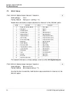
Setting Range:
0 to 1000ms
Factory Default:
50ms
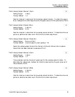
When using a multifunction input to switch between speed and torque mode, D5-06
can be used to allow the analog signals to be modified in preparation for the newly
selected mode.
Upon a change in command (Speed/Torque) the analog input values are retained for
the time set in D5-06 so the analog signals can be changed to accommodate the new
mode. After the D5-06 time elapses the new analog signals are accepted.
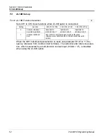
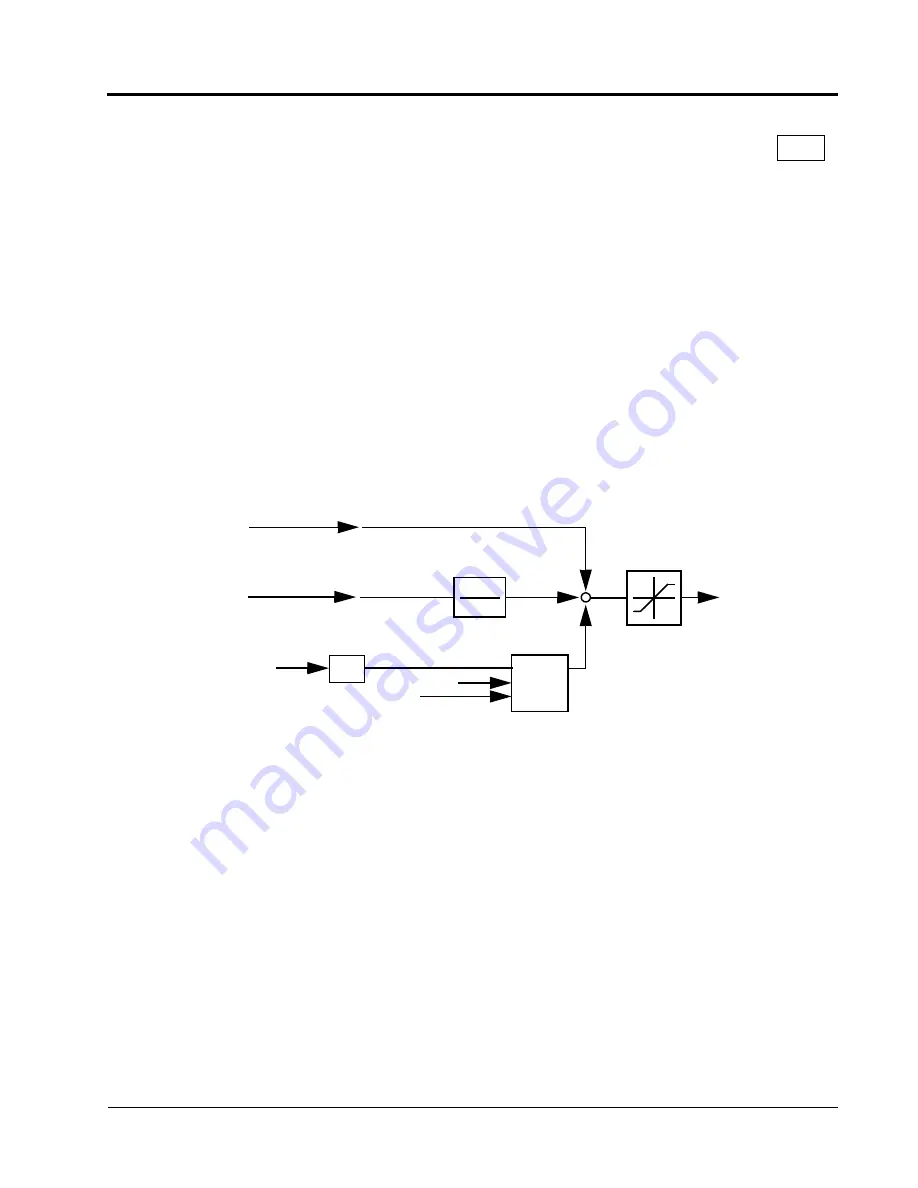
Torque Control Operation
To select torque control, set torque selection
(D5-01)
to “1,” or close the multi-func-
tion contact input set to speed/torque control (
H1-XX
= “71”) and set terminal 16 func-
tion selection to torque reference (
H3-05
= “13”).
*1:
When speed limit selection
(D5-03)
is set to “1,” the master frequency reference input from ter-
minal 13 or 14 becomes the speed limit; when speed limit selection
(D5-03)
is set to “2,” the set
value of
D5-04
becomes the speed limit.
*2:
When terminal 14 function selection is set to torque compensation (
H3-09
= “14”), the terminal l4
set value can be used as the torque compensation value.
When torque reference > 0 and speed limit > 0 (winder application sequence), the fol-
lowing sequence is activated:
•
When [-1 × speed limit bias
(D5-05)
] < motor speed (%) < [speed limit +
D5-05
],
torque control is activated using the set torque reference.
•
When motor speed > [speed limit +
D5-05
], speed limiting circuit outputs a nega-
tive torque reference to prevent the motor speed from increasing.
•
When motor speed < [-l ×
D5-05
], the speed limiting circuit outputs a positive
torque reference to prevent the motor speed from increasing in the reverse direc-
tion.
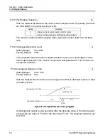
D5-06 Speed/Torque Control Changeover Delay Timer
A
Speed
1
1 + ST
Torque Limit
Iq
+
+
Figure 27 Torque Control Block Diagram
Limiting
Circuit
SFS
T =
D5-02
+
Motor Speed
(D5-05)
Torque
Compensation
*2
Torque
Reference
Speed Limit
*1
Section D: Reference Parameters
D5 Torque Control


