


64
FI
FUEL INJECTION SYSTEM
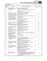
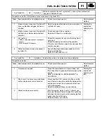
Fault code No.
33
Symptom
Malfunction detected in the primary lead of the cylinder-#1 ignition coil.
Diagnostic code No. d:30 (cylinder-#1 ignition coil)
Order
Item/components and probable cause
Check or maintenance job
Reinstatement
method
1
Connections
• Cylinder-#1 ignition coil coupler
• Wire harness ECU couplers
• Ignition system sub-wire harness coupler
Check the couplers for any pins that may have
pulled out.
Check the locking condition of the couplers.
If there is a malfunction, repair it and connect the
coupler securely.
Starting the
engine and
operating it at
idle.
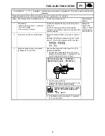
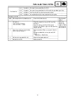
2
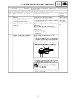
Open or short circuit in wire harness
and/or ignition system sub-wire harness.
Repair or replace if there is an open or short cir-
cuit.
Between the cylinder-#1 ignition coil coupler and
ECU couplers.
Orange – Orange
Red/White – Red/White
3
Detective cylinder-#1 ignition coil.
Execute the diagnostic mode (code No. d:30).
Test the primary and secondary coils for continu-
ity.
Replace if defective.
Refer to “IGNITION SYSTEM” in CHAPTER 8.
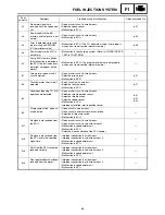
Fault code No.
34
Symptom
Malfunction detected in the primary lead of the cylinder-#2 ignition coil.
Diagnostic code No. d:31 (cylinder-#2 ignition coil)
Order
Item/components and probable cause
Check or maintenance job
Reinstatement
method
1
Connections
• Cylinder-#2 ignition coil coupler
• Wire harness ECU couplers
• Ignition system sub-wire harness coupler
Check the couplers for any pins that may have
pulled out.
Check the locking condition of the couplers.
If there is a malfunction, repair it and connect the
coupler securely.
Starting the
engine and
operating it at
idle.
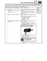
2
Open or short circuit in wire harness
and/or ignition system sub-wire harness.
Repair or replace if there is an open or short cir-
cuit.
Between the cylinder-#2 ignition coil coupler and
ECU couplers.
Gray/Red – Gray/Red
Red/White – Red/White
3
Defective cylinder-#2 ignition coil.
Execute the diagnostic mode (code No. d:31).
Test the primary and secondary coils for continu-
ity.
Replace if defective.
Refer to “IGNITION SYSTEM” in CHAPTER 8.
Summary of Contents for RST90GTY
Page 12: ......
Page 15: ...CABLE ROUTING 102 ...
Page 19: ...ALLMÄN VÄGLEDNING FÖR ÅTDRAGNINGSMOMENT 101 DEFINITION AV ENHETER 101 KABELDRAGNING 102 ...
Page 127: ...FI ...
Page 183: ...FI ...
Page 271: ...SPEC ...
Page 272: ...102 SPEC CABLE ROUTING 8 9 0 A B C E F G C C D 1 2 3 4 5 5 6 7 A B A B ...
Page 294: ......
Page 295: ......