


56
FI
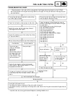
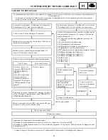
FUEL INJECTION SYSTEM
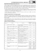
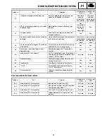
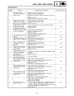
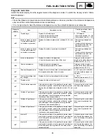
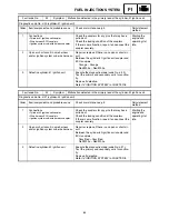
Diagnostic mode table
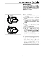
Switch the meter display from the regular mode to the diagnostic mode. To switch the display, refer to “DIAG-
NOSTIC MODE”.
TIP
• Check the intake air temperature and coolant temperature as close as possible to the intake air temperature
sensor and the coolant temperature sensor respectively.
• If it is not possible to check the intake air temperature, use the ambient temperature as reference.
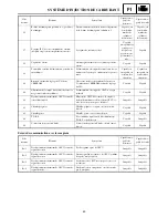
Diagnostic
code No.
Item
Description of action
Checking method or meter
display
d:01
Throttle angle
Displays the throttle angle.
• Check with throttle fully closed.
• Check with throttle fully open.
0 ~ 125 degrees
• Fully closed position (15 ~ 18)
• Fully open position (94 ~ 100)
d:03
Intake air pressure sensor
1 (atmospheric pressure
and intake air pressure)
Displays the intake air pressure for cylinders #1, #2, and
#3.
• Not cranking: atmospheric
pressure
• Cranking: intake air pressure
decreases to less than the
atmospheric pressure.
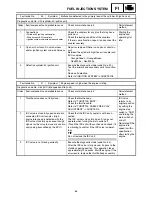
d:04
Intake air pressure sensor
2 (atmospheric pressure
and intake air pressure)
Displays the intake air pressure for cylinder #1.
• Not cranking: atmospheric
pressure
• Cranking: intake air pressure
decreases to less than the
atmospheric pressure.
d:05
Intake air temperature
Displays the intake air temperature.
• Check the temperature in the air filter case.
Compare it to the value dis-
played on the meter. (Minimum
displayed value: –30 [°C])
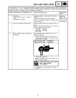
d:06
Coolant temperature
Displays the coolant temperature.
• Check the temperature of the coolant.
Compare it to the value dis-
played on the meter. (Minimum
displayed value: –30 [°C])
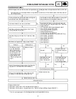
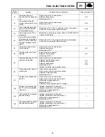
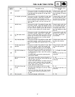
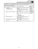
d:07
Snowmobile speed pulse
Displays the cumulative number of snowmobile pulses
that are generated when the track is spun.
(0 ~ 999; resets to 0 after 999)
OK if the numbers appear on
the meter.
d:09
Fuel system voltage (bat-
tery voltage)
Displays the fuel system voltage (battery voltage).
0 ~ 18.7 V
Normally, approximately 12.0 V
d:24
Throttle switch
Displays that the switch is on or off.
Throttle open: on
Throttle closed: off
d:27
Thumb warmer operation
If the grip warmer side of the grip/thumb warmer adjust-
ment switch is pushed, actuates the thumb warmer and
displays the self-diagnosis warning indicator for 120 sec-
onds.
After pushing the switch, check
that the warmer becomes
warm.
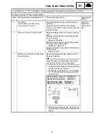
d:30
Cylinder-#1 ignition coil
If the grip warmer side of the grip/thumb warmer adjust-
ment switch is pushed, actuates the cylinder-#1 ignition
coil and displays the self-diagnosis warning indicator
(five times at one-second intervals).
After pushing the switch, check
that a spark is produced five
times.
d:31
Cylinder-#2 ignition coil
If the grip warmer side of the grip/thumb warmer adjust-
ment switch is pushed, actuates the cylinder-#2 ignition
coil and displays the self-diagnosis warning indicator
(five times at one-second intervals).
After pushing the switch, check
that a spark is produced five
times.
d:32
Cylinder-#3 ignition coil
If the grip warmer side of the grip/thumb warmer adjust-
ment switch is pushed, actuates the cylinder-#3 ignition
coil and displays the self-diagnosis warning indicator
(five times at one-second intervals).
After pushing the switch, check
that a spark is produced five
times.
d:36
Injector #1
If the grip warmer side of the grip/thumb warmer adjust-
ment switch is pushed, actuates injector #1 and displays
the self-diagnosis warning indicator (five times at one-
second intervals).
After pushing the switch, check
that the injector operates five
times by listening to its operat-
ing sound.
d:37
Injector #2
If the grip warmer side of the grip/thumb warmer adjust-
ment switch is pushed, actuates injector #2 and displays
the self-diagnosis warning indicator (five times at one-
second intervals).
After pushing the switch, check
that the injector operates five
times by listening to its operat-
ing sound.
Summary of Contents for RST90GTY
Page 12: ......
Page 15: ...CABLE ROUTING 102 ...
Page 19: ...ALLMÄN VÄGLEDNING FÖR ÅTDRAGNINGSMOMENT 101 DEFINITION AV ENHETER 101 KABELDRAGNING 102 ...
Page 127: ...FI ...
Page 183: ...FI ...
Page 271: ...SPEC ...
Page 272: ...102 SPEC CABLE ROUTING 8 9 0 A B C E F G C C D 1 2 3 4 5 5 6 7 A B A B ...
Page 294: ......
Page 295: ......