


47
CL3/CL1
1.
Control Panel U7 Assembly
(Time required: About 5 minutes)
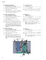
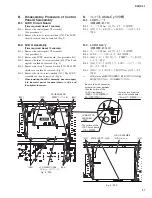
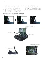
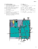
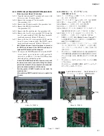
1-1.
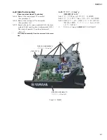
Loosen the two (2) screws marked [130A] on the rear
panel fi rst and then remove the eighteen (18) screws
marked [130B] and the eight (8) screws marked [140].
(Fig. 2)
1.
コンパネ U7 Ass y
(所要時間:約 5 分)
1-1.
リアパネル側の [130A] のネジ 2 本を緩めてから、
[130B] のネジ 18 本と [140] のネジ 8 本を外します。
(図 2)
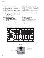
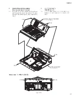
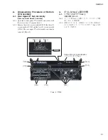
Fig. 2 (図 2)
• Rear view
(リア側から見た図)
[130B]
[130B]
[130B]
[130B]
[140]
CONTROL PANEL U7 ASSEMBLY
(コンパネ U7 Ass y)
BOTTOM U7 ASSEMBLY
(ボトム U7 Ass y)
[130A]
[130A]
Summary of Contents for CL3
Page 7: ...7 CL3 CL1 DIMENSIONS CL3 CL1 648 15 201 130 299 667 839 15 201 130 299 667 Unit mm...
Page 95: ...95 CL3 CL1 CPU Circuit Board Pattern side to DSP CN101 2NA WY67750 1...
Page 101: ...101 CL3 CL1 DNTU Circuit Board Pattern side Scale 80 100 2NA WZ20390 5...
Page 102: ...CL3 CL1 102 2NA WY63530 FX Circuit Board WR 63 1 Component side Scale 95 100...
Page 103: ...103 CL3 CL1 2NA WY63530 FX Circuit Board Pattern side Scale 95 100...
Page 105: ...105 CL3 CL1 HAAD Circuit Board Pattern side Scale 90 100 2NA WY64340 2...
Page 107: ...107 CL3 CL1 2NA WY63490 Component side JK Circuit Board WR 63 1...
Page 109: ...109 CL3 CL1 Component side TBPHN Circuit Board WR 06 1 WR 63 1 2NA WY64360 1...
Page 110: ...CL3 CL1 110 Component side PN8 Circuit Board to FD8 CN902 or FD8CN CN902 2NA WY53120 2...
Page 118: ...CL3 CL1 118 Component side PNENL Circuit Board to PN8 CN001 2NA WY53130 1...
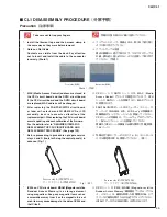
Page 160: ...CL3 CL1 160 1 18 LCD Test LCD LCD 1 3 2 9 5 OK NG 1 2 H 3 O X O 4 BOX 5x4...
Page 382: ...7 MBCL CIRCUIT BOARDS A A A A 2NA WY53200 1 MB Circuit Board Component side...
Page 383: ...MBCL 8 MB Circuit Board DSUB PH CONNECTOR ASSEMBLY B B B B 2NA WY53200 1 Pattern side...


