


66
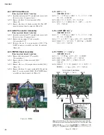
CL3/CL1
[190]
PN2
PN PUSH ANGLE 2
(PN PUSH 金具 2)
PN PUSH ANGLE 8
(PN PUSH 金具 8)
[100] x3
[170]
PN PUSH ANGLE 8
(PN PUSH 金具 8)
[170]
[80] x6
PN8 ADDED BUTTON
(PN8 ボタン付)
PN8
z
x
[80] x6
PN8 ADDED BUTTON
(PN8 ボタン付)
PN8
z
z
x
x
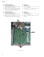
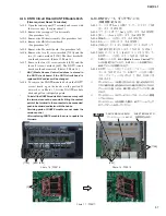
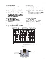
B-9. PNM シート
(所要時間:約 8 分)
B-9-1. コンパネ U7 Ass y を外します。(1 項参照)
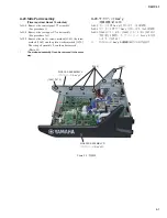
B-9-2. [650] のノブ 1 個を外します。(図 7)
B-9-3. [140] のネジ 10 本を外して、PNM シートを外します。
(図 9)
※
PNM シートを取り付ける際は、図 9 に示す
z
、
x
の順
にネジを締めてから他のネジを締めてください。
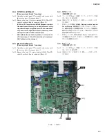
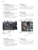
B-10. PNI シート
(所要時間:約 7 分)
B-10-1. コンパネ U7 Ass y を外します。(1 項参照)
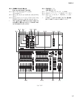
B-10-2. [120] のネジ 5 本を外して、PNI シートを外します。
(図 9)
※
PNI シートを取り付ける際は、図 9 に示す
z
、
x
の順に
ネジを締めてから他のネジを締めてください。
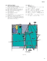
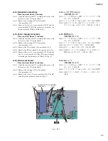
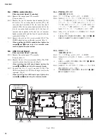
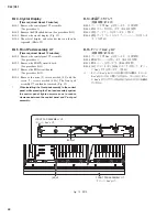
B-11. PN2 シート
(所要時間:約 8 分)
B-11-1. コンパネ U7 Ass y を外します。(1 項参照)
B-11-2. FD2 シートを外します。(B-6 項参照)
B-11-3. [550B] のエンコーダーノブ 2 個を外します。
(図 7)
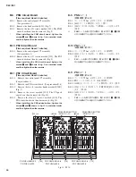
B-11-4. [190] のネジ 1 本を外して、PNPUSH 金具 2 を外し
ます。(図 10)
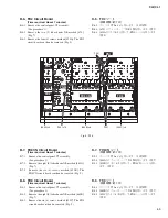
B-11-5. [100] のネジ 3 本を外して、PN2 シートを外します。
(図 10)
※
PN2 シートを取り付ける際は、図 10 に示す
z
、
x
の順
にネジを締めてから他のネジを締めてください。
B-9. PNM Circuit Board
(Time required: About 8 minutes)
B-9-1. Remove the control panel U7 assembly.
(See procedure 1)
B-9-2. Remove the knob marked [650]. (Fig. 7)
B-9-3. Remove the ten (10) screws marked [140]. The PNM
circuit board can then be removed. (Fig. 9)
*
When installing the PNM circuit board, tighten the
screws
z
and
x
shown in fi g. 9 in numerical order
and then tighten the other screws.
B-10. PNI Circuit Board
(Time required: About 7 minutes)
B-10-1. Remove the control panel U7 assembly.
(See procedure 1)
B-10-2. Remove the fi ve (5) screws marked [120]. The PNI
circuit board can then be removed. (Fig. 9)
*
When installing the PNI circuit board, tighten the
screws
z
and
x
shown in fi g. 9 in numerical order
and then tighten the other screws.
B-11. PN2 Circuit Board
(Time required: About 8 minutes)
B-11-1. Remove the control panel U7 assembly.
(See procedure 1)
B-11-2. Remove the FD2 circuit board. (See procedure B-6)
B-11-3. Remove the two (2) encorder knobs marked [550B].
(Fig. 7)
B-11-4. Remove the screw marked [190]. The PN push
angle 2 can then be removed. (Fig. 10)
B-11-5. Remove the three (3) screws marked [100]. The
PN2 circuit board can then be removed. (Fig. 10)
*
When installing the PN2 added button, tighten the
screws
z
and
x
shown in fi g. 10 in numerical order
and then tighten the other screws.
Fig. 10 (図 10)
Summary of Contents for CL3
Page 7: ...7 CL3 CL1 DIMENSIONS CL3 CL1 648 15 201 130 299 667 839 15 201 130 299 667 Unit mm...
Page 95: ...95 CL3 CL1 CPU Circuit Board Pattern side to DSP CN101 2NA WY67750 1...
Page 101: ...101 CL3 CL1 DNTU Circuit Board Pattern side Scale 80 100 2NA WZ20390 5...
Page 102: ...CL3 CL1 102 2NA WY63530 FX Circuit Board WR 63 1 Component side Scale 95 100...
Page 103: ...103 CL3 CL1 2NA WY63530 FX Circuit Board Pattern side Scale 95 100...
Page 105: ...105 CL3 CL1 HAAD Circuit Board Pattern side Scale 90 100 2NA WY64340 2...
Page 107: ...107 CL3 CL1 2NA WY63490 Component side JK Circuit Board WR 63 1...
Page 109: ...109 CL3 CL1 Component side TBPHN Circuit Board WR 06 1 WR 63 1 2NA WY64360 1...
Page 110: ...CL3 CL1 110 Component side PN8 Circuit Board to FD8 CN902 or FD8CN CN902 2NA WY53120 2...
Page 118: ...CL3 CL1 118 Component side PNENL Circuit Board to PN8 CN001 2NA WY53130 1...
Page 160: ...CL3 CL1 160 1 18 LCD Test LCD LCD 1 3 2 9 5 OK NG 1 2 H 3 O X O 4 BOX 5x4...
Page 382: ...7 MBCL CIRCUIT BOARDS A A A A 2NA WY53200 1 MB Circuit Board Component side...
Page 383: ...MBCL 8 MB Circuit Board DSUB PH CONNECTOR ASSEMBLY B B B B 2NA WY53200 1 Pattern side...


