


57
CL3/CL1
A-10. DNTU Circuit Board, DANTE Module 64ch
(Time required: About 18 minutes)
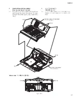
A-10-1. Open the control panel U7 assembly and secure with
the service stays. (See procedure 1)
A-10-2. Remove the rear upper U7 sub assembly.
(See procedure A-1)
A-10-3. Remove the JK sheet assembly. (See procedure A-6)
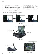
A-10-4. Remove the HAAD circuit board.
(See procedure A-7)
A-10-5. Remove the DA circuit board. (See procedure A-9)
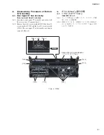
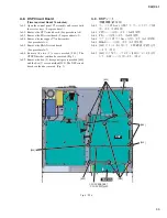
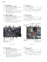
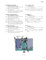
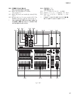
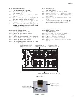
A-10-6. Remove the two (2) screws marked [710A] and the
two (2) screws marked [710B]. The sheet bracket R
can then be removed. (Photo 15, Photo 16)
A-10-7. Remove the four (4) screws marked [650] and the
three (3) screws marked [660]. The DNTU circuit
board can then be removed. (Photo 15, Photo 16)
*
MAC (Media Access Control) address is stored in
the DNTU circuit board. If the DNTU circuit board is
replaced, MAC address will be changed.
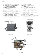
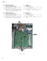
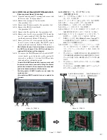
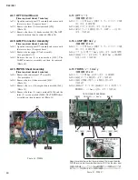
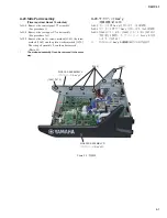
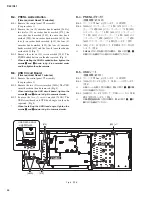
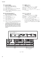
A-10-8. To remove the DANTE module 64ch on the DNTU
circuit board, open the hooks on the portion D
outward as in Photo 17, lift the DANTE module
64ch and pull out obliquely upward.
*
To install the DANTE module 64ch, insert securely until
the terminal cannot be seen while fitting the contact
point of the terminal to the connector to be connected,
push in backward and fasten with the hooks.
*
Servicing parts of DANTE module are not under the
version control
.
After replacing DANTE module, be sure to update the
fi rmware.
A-10. DNTU シート、ダンテモジュール
(所要時間:約 18 分)
A-10-1. コンパネ U7 Ass y を開けて、サービスステイで固
定します。(1 項参照)
A-10-2. リア上パネ U7 サブ Ass y を外します。
(A-1 項参照)
A-10-3. JK シート Ass y を外します。(A-6 項参照)
A-10-4. HAAD シ−トを外します。(A-7 項参照)
A-10-5. DA シ−トを外します。(A-9 項参照)
A-10-6. [710A] のネジ 2 本と [710B] のネジ 2 本を外して、
基板固定金具 R を外します。(写真 15、写真 16)
A-10-7. [650] の ネ ジ 4 本 と [660] の ネ ジ 3 本 を 外 し て、
DNTU シートを外します。(写真 15、写真 16)
※
DNTU シートには、MAC (Media Access Control) アド
レスが設定されています。DNTU シートを交換すると、
MAC アドレスが変更されます。
A-10-8. DNTU シートに付いているダンテモジュールを外
すには、写真 17 のように D 部のフックを外に開い
てダンテモジュールを浮かせて、斜め上方向に引
き抜きます。
※
ダンテモジュールを取り付けるには、差し込み先のコネ
クタに端子の接点を合わせながら端子が見えなくなるま
でしっかりと差し込み、奥に押し込んでフックに引っ掛
けます。
※
ダンテモジュールのサービスパーツは、バージョン管理
しておりません。
ダンテモジュールを交換した際は、必ずファームウェア
のアップデートを行ってください。
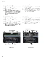
Photo 15 (写真 15)
Photo 16 (写真 16)
Photo 17 (写真 17)
[650] [650]
[710A]
[D]
[660]
DANTE MODULE 64CH
(ダンテモジュール 64CH)
DNTU
[710B]
SHEET BRACKET R
(基板固定金具 R)
Summary of Contents for CL3
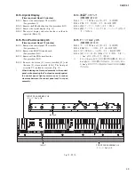
Page 7: ...7 CL3 CL1 DIMENSIONS CL3 CL1 648 15 201 130 299 667 839 15 201 130 299 667 Unit mm...
Page 95: ...95 CL3 CL1 CPU Circuit Board Pattern side to DSP CN101 2NA WY67750 1...
Page 101: ...101 CL3 CL1 DNTU Circuit Board Pattern side Scale 80 100 2NA WZ20390 5...
Page 102: ...CL3 CL1 102 2NA WY63530 FX Circuit Board WR 63 1 Component side Scale 95 100...
Page 103: ...103 CL3 CL1 2NA WY63530 FX Circuit Board Pattern side Scale 95 100...
Page 105: ...105 CL3 CL1 HAAD Circuit Board Pattern side Scale 90 100 2NA WY64340 2...
Page 107: ...107 CL3 CL1 2NA WY63490 Component side JK Circuit Board WR 63 1...
Page 109: ...109 CL3 CL1 Component side TBPHN Circuit Board WR 06 1 WR 63 1 2NA WY64360 1...
Page 110: ...CL3 CL1 110 Component side PN8 Circuit Board to FD8 CN902 or FD8CN CN902 2NA WY53120 2...
Page 118: ...CL3 CL1 118 Component side PNENL Circuit Board to PN8 CN001 2NA WY53130 1...
Page 160: ...CL3 CL1 160 1 18 LCD Test LCD LCD 1 3 2 9 5 OK NG 1 2 H 3 O X O 4 BOX 5x4...
Page 382: ...7 MBCL CIRCUIT BOARDS A A A A 2NA WY53200 1 MB Circuit Board Component side...
Page 383: ...MBCL 8 MB Circuit Board DSUB PH CONNECTOR ASSEMBLY B B B B 2NA WY53200 1 Pattern side...


