


34
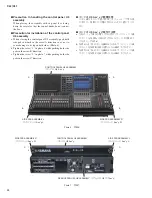
CL3/CL1
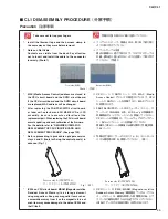
Fig. 4 (図 4)
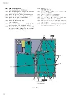
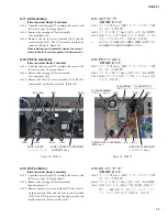
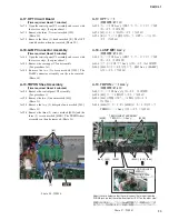
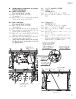
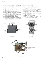
A-14. レセプタクル Ass y
(所要時間:約 9 分)
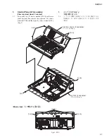
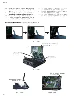
A-14-1. コンパネ U5 Ass y を開けて、サービスステイで固
定します。(1 項参照)
A-14-2. リア上パネ U5 サブ Ass y を外します。
(A-1 項参照)
A-14-3. [290] のネジ 4 本と [300] のネジ 1 本を外して、レ
セプタクル Ass y を外します。(写真 18、写真 19)
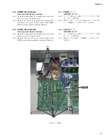
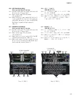
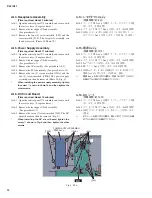
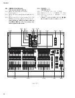
A-15. 電源 Ass y
(所要時間:約 11 分)
A-15-1. コンパネ U5 Ass y を開けて、サービスステイで固
定します。(1 項参照)
A-15-2. リア上パネ U5 サブ Ass y を外します。
(A-1 項参照)
A-15-3. AC アセンブリを外します。(A-11 項参照)
A-15-4. PS ファン Ass y を外します。(A-12 項参照)
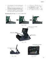
A-15-5. [190A] のネジ 2 本と [190B] のネジ 5 本を外して、
電源 Ass y を外します。(写真 18、図 4)
※
電源 Ass y を取り付ける際は、写真 18 に示す
z
のネジ
を締めてから他のネジを締めてください。
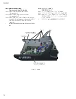
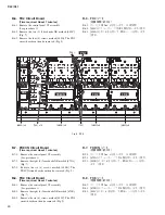
A-16. DC シート
(所要時間:約 10 分)
A-16-1. コンパネ U5 Ass y を開けて、サービスステイで固
定します。(1 項参照)
A-16-2. リア上パネ U5 サブ Ass y を外します。
(A-1 項参照)
A-16-3. [240] のネジ 7 本を外して、DC シートを外します。
(図 4)
※
DC シートを取り付ける際は、図 4 に示す
z
のネジを締
めてから他のネジを締めてください。
A-14. Receptacle Assembly
(Time required: About 9 minutes)
A-14-1. Open the control panel U5 assembly and secure with
the service stays. (See procedure 1)
A-14-2. Remove the rear upper U5 sub assembly.
(See procedure A-1)
A-14-3. Remove the four (4) screws marked [290] and the
screw marked [300]. The receptacle assembly can
then be removed. (Photo 18, Photo 19)
A-15. Power Supply Assembly
(Time required: About 11 minutes)
A-15-1. Open the control panel U5 assembly and secure with
the service stays. (See procedure 1)
A-15-2. Remove the rear upper U5 sub assembly.
(See procedure A-1)
A-15-3. Remove the AC assembly. (See procedure A-11)
A-15-4. Remove the PS fan assembly. (See procedure A-12)
A-15-5. Remove the two (2) screws marked [190A] and the
five (5) screws marked [190B]. The power supply
assembly can then be removed. (Photo 18, Fig. 4)
*
When installing the power supply assembly, tighten
the screw
z
shown in Photo 18 and then tighten the
other screws.
A-16. DC Circuit Board
(Time required: About 10 minutes)
A-16-1. Open the control panel U5 assembly and secure with
the service stays. (See procedure 1)
A-16-2. Remove the rear upper U5 sub assembly.
(See procedure A-1)
A-16-3. Remove the seven (7) screws marked [240]. The DC
circuit board can then be removed. (Fig.
4
)
*
When installing the DC circuit board, tighten the
screw
z
shown in Fig. 4 and then tighten the other
screws.
POWER SUPPLY ASSEMBLY
(電源 Ass y)
[190B]
[190B]
[240]
[240]
DC
z
Summary of Contents for CL3
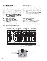
Page 7: ...7 CL3 CL1 DIMENSIONS CL3 CL1 648 15 201 130 299 667 839 15 201 130 299 667 Unit mm...
Page 95: ...95 CL3 CL1 CPU Circuit Board Pattern side to DSP CN101 2NA WY67750 1...
Page 101: ...101 CL3 CL1 DNTU Circuit Board Pattern side Scale 80 100 2NA WZ20390 5...
Page 102: ...CL3 CL1 102 2NA WY63530 FX Circuit Board WR 63 1 Component side Scale 95 100...
Page 103: ...103 CL3 CL1 2NA WY63530 FX Circuit Board Pattern side Scale 95 100...
Page 105: ...105 CL3 CL1 HAAD Circuit Board Pattern side Scale 90 100 2NA WY64340 2...
Page 107: ...107 CL3 CL1 2NA WY63490 Component side JK Circuit Board WR 63 1...
Page 109: ...109 CL3 CL1 Component side TBPHN Circuit Board WR 06 1 WR 63 1 2NA WY64360 1...
Page 110: ...CL3 CL1 110 Component side PN8 Circuit Board to FD8 CN902 or FD8CN CN902 2NA WY53120 2...
Page 118: ...CL3 CL1 118 Component side PNENL Circuit Board to PN8 CN001 2NA WY53130 1...
Page 160: ...CL3 CL1 160 1 18 LCD Test LCD LCD 1 3 2 9 5 OK NG 1 2 H 3 O X O 4 BOX 5x4...
Page 382: ...7 MBCL CIRCUIT BOARDS A A A A 2NA WY53200 1 MB Circuit Board Component side...
Page 383: ...MBCL 8 MB Circuit Board DSUB PH CONNECTOR ASSEMBLY B B B B 2NA WY53200 1 Pattern side...


