


CL3/CL1
166
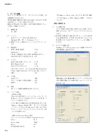
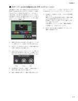
To reset settings to the factory shipment state, execute “forced initialization” by turning on the power switch while holding down the
[STORE]
and
[INC]
keys simultaneously.
When the forced initialization has been completed, the con
fi
rmation message “Flash Memory Initializing Finished” will appear. Then
press the
[CLOSE]
key, and the normal screen appears followed by the version of DANTE. Wait until the ACCESS indicator at the
upper right turns off and that’s the end of the procedure.
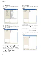
CL also has 2 types of initialization mode. They are “INITIALIZE ALL MEMORIES” and “INITIALIZE CURRENT MEMORIES”.
They are available to users and can be used as necessary. To use these modes, turn on the power switch while holding down the
[STORE]
key, and the special mode screen will appear. Then select the mode and execute initialization.
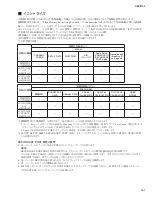
The following table shows types of memory initialized in above 3 initialization modes.
(
○
marked memory is initialized)
Initialization
mode
Memory type
MRAM
CURRENT
SCENE
SETUP DATA
PORT TRIM
DIO status
Dante Setup
-CONSOLE ID
-SECONDARY
PORT mode
Dante module
(Brooklyn
II
)
setting data
FORCED
INITIALIZATION
(Factory default)
○
○
○
○
○
○
INITIALIZE
ALL
MEMORIES
○
○
○
—
—
—
INITIALIZE
CURRENT
MEMORIES
○
○
○
—
—
—
Initialization
mode
Memory type
FRASH ROM
Model
identifi cation
SCENE1-300
DATA
LIBRARY DATA
FADER
CALIBRATION
NAME BL
CALIBRATION
CH COLOR
CALIBRATION
USER
BITMAP
FORCED
INITIALIZATION
(Factory default)
—
○
○
—
—
—
○
INITIALIZE
ALL
MEMORIES
—
○
○
—
—
—
○
INITIALIZE
CURRENT
MEMORIES
—
—
—
—
—
—
—
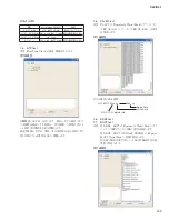
* When the forced initialization (as when shipped from the factory) is executed, settings of the DANTE module will be as follows.
1. The device name of the DANTE module is reset to BLKN II xxxxxx and then renamed to Y001 YAMAHA CL x-xxxxxx after
restarting. The DANTE device name must be changed for correct connection of the CL series and I/O rack.
2. The network setting of the DANTE SECONDARY PORT is reset to [DAISY CHAIN].
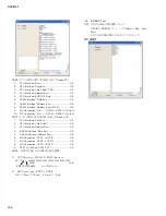
* When the SECONDARY PORT setting or the IC of the CL series or I/O rack has been changed on the DANTE SETUP screen, it is
necessary to turn on the power again.
Changing SECONDARY PORT setting
1. Disconnect the Ethernet cable from the DANTE terminal or the CL series I/O rack.
NOTE
When changing the SECONDARY PORT setting, it is also necessary to change the cable connection between the CL series and I/O rack.
For example, if the setting is changed to DAISY CHAIN with cable connection for REDUNDANT setting as it is, it will be impossible
to send/receive the sound.
Be sure to disconnect the cable before changing the setting.
2. Check the REDUNDANT setting of the CL series and DIP switch setting of the I/O rack.
3. Turn on the power to the CL series and I/O rack again.
4. After waiting for about 1 minute, connect the Ethernet cable to the DANTE terminal of the I/O rack
fi
rst. Then, after waiting for
about 20 seconds, connect the Ethernet cable to the DANTE terminal of the CL series.
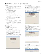
■
INITIALIZATION
Summary of Contents for CL3
Page 7: ...7 CL3 CL1 DIMENSIONS CL3 CL1 648 15 201 130 299 667 839 15 201 130 299 667 Unit mm...
Page 95: ...95 CL3 CL1 CPU Circuit Board Pattern side to DSP CN101 2NA WY67750 1...
Page 101: ...101 CL3 CL1 DNTU Circuit Board Pattern side Scale 80 100 2NA WZ20390 5...
Page 102: ...CL3 CL1 102 2NA WY63530 FX Circuit Board WR 63 1 Component side Scale 95 100...
Page 103: ...103 CL3 CL1 2NA WY63530 FX Circuit Board Pattern side Scale 95 100...
Page 105: ...105 CL3 CL1 HAAD Circuit Board Pattern side Scale 90 100 2NA WY64340 2...
Page 107: ...107 CL3 CL1 2NA WY63490 Component side JK Circuit Board WR 63 1...
Page 109: ...109 CL3 CL1 Component side TBPHN Circuit Board WR 06 1 WR 63 1 2NA WY64360 1...
Page 110: ...CL3 CL1 110 Component side PN8 Circuit Board to FD8 CN902 or FD8CN CN902 2NA WY53120 2...
Page 118: ...CL3 CL1 118 Component side PNENL Circuit Board to PN8 CN001 2NA WY53130 1...
Page 160: ...CL3 CL1 160 1 18 LCD Test LCD LCD 1 3 2 9 5 OK NG 1 2 H 3 O X O 4 BOX 5x4...
Page 382: ...7 MBCL CIRCUIT BOARDS A A A A 2NA WY53200 1 MB Circuit Board Component side...
Page 383: ...MBCL 8 MB Circuit Board DSUB PH CONNECTOR ASSEMBLY B B B B 2NA WY53200 1 Pattern side...


