


37
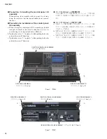
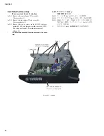
CL3/CL1
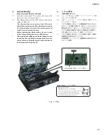
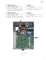
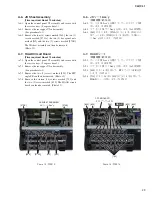
Fig. 5 (図 5)
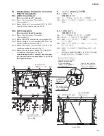
B.
コンパネ U5 Ass y の分解
B-1. LCDC シート
(所要時間:約 7 分)
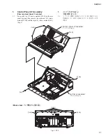
B-1-1. コンパネ U5 Ass y を外します。(1 項参照)
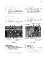
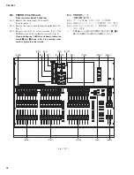
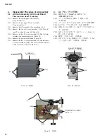
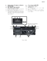
B-1-2. [270] のネジ 4 本を外して、LCDC シートを外します。
(図 5)
B-2. LCD U Ass y
(所要時間:約 10 分)
B-2-1. コンパネ U5 Ass y を外します。(1 項参照)
B-2-2. LCDC シートを外します。(B-1 項参照)
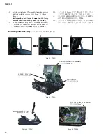
B-2-3. [440] のネジ 3 本を外して、P 補助アングル B を外
します。(図 5)
B-2-4. [250] のネジ 7 本を外して、LCD シールドケースを
外します。(図 5)
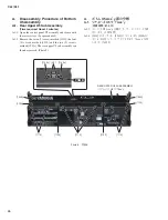
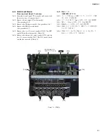
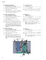
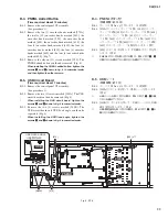
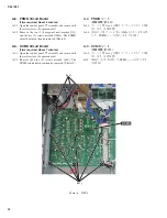
B-2-5. [210] のネジ 6 本を外して、LCD U Ass y を外します。
(図 6)
※
LCD U Ass y を取り付ける際は、図 6 に示すパネルの金
具に当て付けてから、ネジを締めてください。
B.
Disassembly Procedure of Control
Panel U5 Assembly
B-1. LCDC Circuit Board
(Time required: About 7 minutes)
B-1-1. Remove the control panel U5 assembly.
(See procedure 1)
B-1-2. Remove the four (4) screws marked [270]. The LCDC
circuit board can then be removed. (Fig. 5)
B-2. LCD U Assembly
(Time required: About 10 minutes)
B-2-1. Remove the control panel U5 assembly.
(See procedure 1)
B-2-2. Remove the LCDC circuit board. (See procedure B-1)
B-2-3. Remove the three (3) screws marked [440]. The P sub
angle B can then be removed. (Fig. 5)
B-2-4. Remove the seven (7) screws marked [250]. The LCD
shield case can then be removed. (Fig. 5)
B-2-5. Remove the six (6) screws marked [210]. The LCD U
assembly can then be removed. (Fig. 6)
*
When installing the LCD U assembly, be sure to apply
it to the metal part of the panel shown in fi g. 6 and
then tighten the screw.
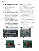
Be sure to fix the connector
assembly at lower positions
than the surface of the
LCDC circuit board.
(束線は、LCDC 基板面より
低い位置で固定のこと。)
12mm or less (from the
end of the circuit board)
(12mm 以下(基板端より))
CONNECTOR
ASSEMBLY
(束線)
The surface of the
LCDC circuit board
(LCDC 基板面)
[440]
P SUB ANGLE B
(P 補助アングル B)
LCDC
[250]
[250]
[270]
[250]
LCD SHIELD CASE
(LCD シールドケース)
LCD U ASSEMBLY
(LCD U Ass y)
[210]
METAL PART
(金具)
[210]
Fig. 6 (図 6)
Summary of Contents for CL3
Page 7: ...7 CL3 CL1 DIMENSIONS CL3 CL1 648 15 201 130 299 667 839 15 201 130 299 667 Unit mm...
Page 95: ...95 CL3 CL1 CPU Circuit Board Pattern side to DSP CN101 2NA WY67750 1...
Page 101: ...101 CL3 CL1 DNTU Circuit Board Pattern side Scale 80 100 2NA WZ20390 5...
Page 102: ...CL3 CL1 102 2NA WY63530 FX Circuit Board WR 63 1 Component side Scale 95 100...
Page 103: ...103 CL3 CL1 2NA WY63530 FX Circuit Board Pattern side Scale 95 100...
Page 105: ...105 CL3 CL1 HAAD Circuit Board Pattern side Scale 90 100 2NA WY64340 2...
Page 107: ...107 CL3 CL1 2NA WY63490 Component side JK Circuit Board WR 63 1...
Page 109: ...109 CL3 CL1 Component side TBPHN Circuit Board WR 06 1 WR 63 1 2NA WY64360 1...
Page 110: ...CL3 CL1 110 Component side PN8 Circuit Board to FD8 CN902 or FD8CN CN902 2NA WY53120 2...
Page 118: ...CL3 CL1 118 Component side PNENL Circuit Board to PN8 CN001 2NA WY53130 1...
Page 160: ...CL3 CL1 160 1 18 LCD Test LCD LCD 1 3 2 9 5 OK NG 1 2 H 3 O X O 4 BOX 5x4...
Page 382: ...7 MBCL CIRCUIT BOARDS A A A A 2NA WY53200 1 MB Circuit Board Component side...
Page 383: ...MBCL 8 MB Circuit Board DSUB PH CONNECTOR ASSEMBLY B B B B 2NA WY53200 1 Pattern side...


