PATCH screen
284
Reference section
Patch OUT page
Patch signals to output jacks/output channels
Assign output signals to the OMNI
OUT connectors, STEREO OUT con-
nectors, DIGITAL STEREO OUT con-
nector, and the output channels of I/O
card.
• [PATCH] key
→
[F2] (Patch OUT) key
• Repeatedly press the [PATCH] key
until the display shown at right
appears.
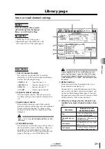
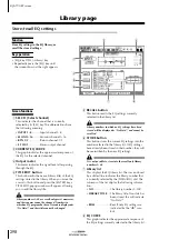
A
OMNI OUT ASSIGN
B
OPTION I/O SLOT OUT ASSIGN
In these areas you can select the signals that will
be assigned to the OMNI OUT 1–4 connectors
and to the output channels of an I/O card installed
in the OPTION I/O slot, respectively. The follow-
ing signals can be assigned.
C
D.ST OUT ASSIGN (Digital stereo out
assign)
D
ST OUT ASSIGN (Stereo out assign)
In these areas you can select the pairs of output
signals that will be assigned to the DIGITAL STE-
REO OUT connector and STEREO OUT connec-
tor, respectively. The following signals can be
assigned.
4
1
3
2
Display
Signal type
ST L/ST R
Stereo output channel L or R
BUS 1 – BUS 8
Bus 1–8
DIR 1 – DIR 8
Direct output of input chan-
nels 1–8
AUX 1 – AUX 6
AUX buses 1–6
RDR 1 – RDR 16
Direct output of tracks 1–16
Display
Signal type
ST L/R
Stereo output channel (L/R)
BUS 1/2 – BUS 7/8
Buses 1/2–7/8
DIR 1/2 – DIR 7/8
Direct output of input chan-
nels 1/2–7/8
AUX 1/2 – AUX 5/6
AUX buses 1/2–5/6
RDR 1/2 – RDR 15/
16
Direct output of tracks 1/2–
15/16


