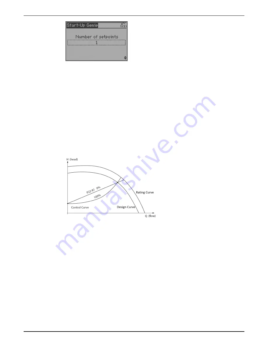
Flow Compensation Setup
As flow in a pumping system increases, the system friction head losses also increase.
Friction head loss is higher in systems with increased pipe lengths or decreased pipe size.
The impact of this head loss is that the pressure at different points in the system will vary
depending on flow rate and the distance from the pump. The loss will be most significant
in the zones farthest from the pump. The controller’s internal Flow Compensation function
is used to correct the effect of friction head loss in the system. The flow compensation
function calculates a control curve based on pump and system parameters. The controller
actively adjusts the setpoint along the control curve based on the speed of the pump.
Since a change in speed is proportional to a change in flow, the controller effectively
adjusts the setpoint based on a change in speed. A change in pressure varies with the
square of the change in speed or flow so a quadratic (square) compensation factor is used
to adjust the setpoint. Parameter
[22-81] Square-linear Curve Approximation
can be
modified to adjust the control curve between a linear (0%) and quadratic (100%). Note
that 100% quadratic is the ideal compensation curve. The diagram below illustrates this
concept. The rating curve is the pump performance curve at rated speed. The design
curve is the system curve at design speed.
Figure 88: Flow compensation control curve
The flow compensation function requires some system parameters to be set in the
controller to accurately model the control curve. Parameters must be set based on the
design of the system in order to properly configure this function. The parameters that are
required to be configured will depend on whether the speed at the design point is
known. If the speed at the design point is known, set
[22-82] Work Point Calculation
to
disabled. Set the
[22-84] Speed at No Flow [Hz]
and
[22-87] Pressure at No-Flow Speed
,
which correlate to point A on the diagram below. The intersection of the system
[20-21]
Setpoint
and
[22-86] Speed at Design Point [Hz]
correlates with point B. With this
information the controller can then calculate the control curve. Refer to the diagram
below.
6 Operation
Aquavar
®
Intelligent Pump Controller - 150 HP to 600 HP INSTRUCTION MANUAL
105
Summary of Contents for Aquavar
Page 1: ...INSTRUCTION MANUAL IM273 Rev C Aquavar Intelligent Pump Controller 150 HP to 600 HP...
Page 2: ......
Page 171: ......


