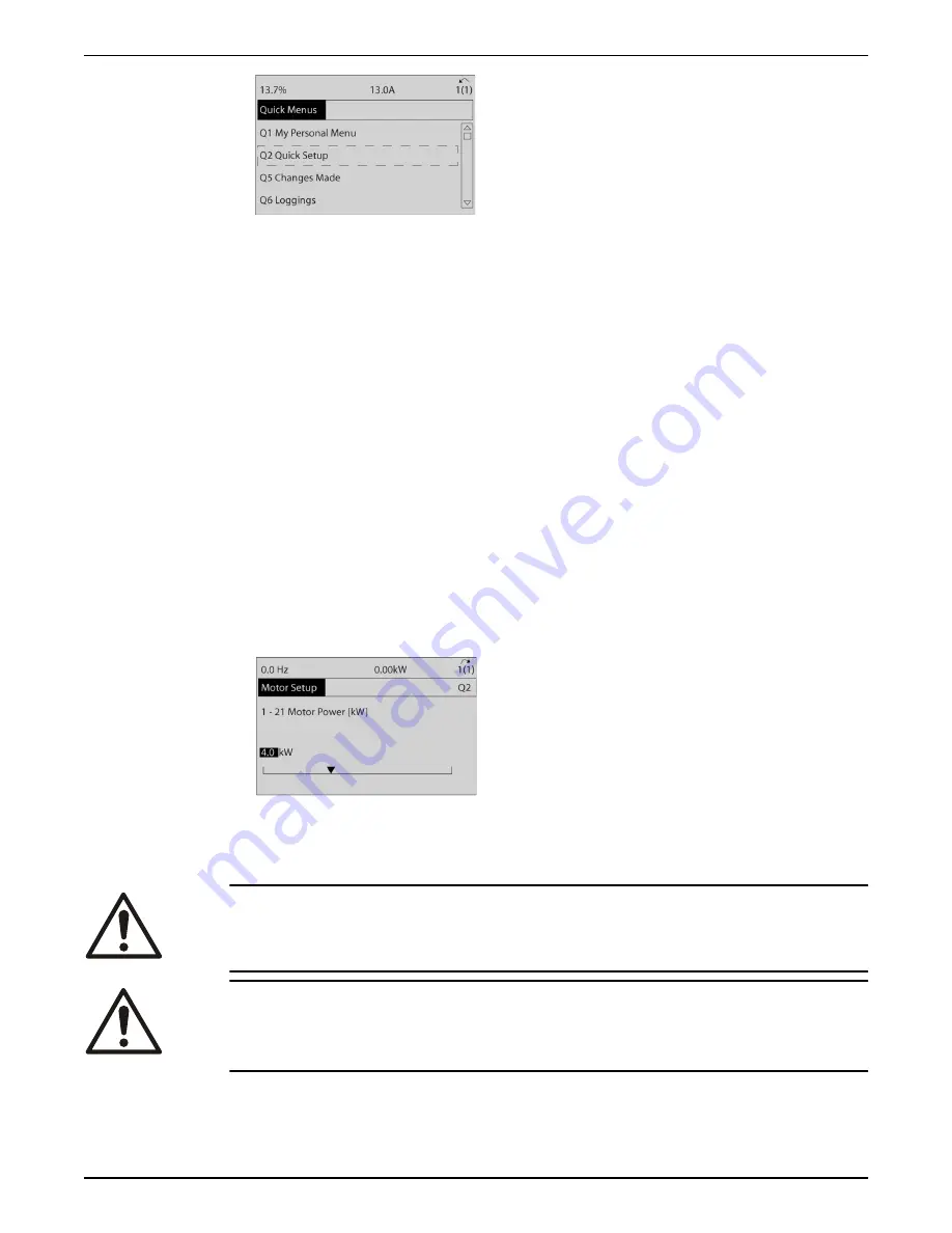
Figure 94: Quick menus
8. Select language and press [OK].
9. A jumper wire should be in place between control terminals 12 and 27. If this is the
case, leave
5–12 Terminal 27 Digital Input
at factory default. Otherwise select
No
Operation
. For frequency converters with an optional Xylem bypass, no jumper wire is
required.
10.
3–02 Minimum Reference
11.
3–03 Maximum Reference
12.
3–41 Ramp 1 Ramp Up Time
13.
3–42 Ramp 1 Ramp Down Time
14.
3–13 Reference Site
. Linked to Hand/Auto* Local
6.7 Induction motor setup
Enter the motor data in parameters 1–20/1–21 to 1–25. The information can be found on
the motor nameplate.
1. –
1–20 Motor Power [kW]
or
1–21 Motor Power [HP]
–
1–22 Motor Voltage
–
1–23 Motor Frequency
–
1–24 Motor Current
–
1–25 Motor Nominal Speed
Figure 95: Motor setup
6.8 PM motor setup
CAUTION:
Only use PM motor with fans and pumps.
WARNING:
WINDMILLING! Unintended rotation of permanent magnet motors causes a risk of
personal injuty and equipment damage. Ensure permanent magnet motors are blocked
to prevent unintended rotation.
Initial programming steps
1. Activate PM motor operation
1–10 Motor Construction
, select
[1] PM, non salient SPM
2. Make sure to set
0–02 Motor Speed Unit
to
[0] RPM
6 Operation
Aquavar
®
Intelligent Pump Controller - 150 HP to 600 HP INSTRUCTION MANUAL
125
Summary of Contents for Aquavar
Page 1: ...INSTRUCTION MANUAL IM273 Rev C Aquavar Intelligent Pump Controller 150 HP to 600 HP...
Page 2: ......
Page 171: ......


