MNC-0300-011
17 of 26
Revision H
Unpacking and Installation
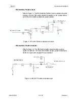
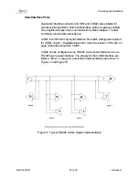
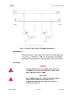
Figure 9, RF Inhibit with switch A opened
RF Output Analog output
The Digital Monitor and Control provides the analog output voltage
correspondence to the RF output power. The conversion formula is:
V
o
= 10
(PdBm – 47.27)/19.05
or P
dBm
= 47.27 + 19.05
[log10(Vo)]
With P
dBm
= RF Output power in dBm
Waveguide Switch connection (Digital SSPAs Only)
Table 3 Lists the Waveguide Switch Connector Pinouts. Figure 10 shows
the pin and socket layout of the Waveguide Switch Interface Connector
and the Waveguide Switch Mating Connector.
Summary of Contents for XTS-200C
Page 10: ...MNC 0000 010 2 Revision A6...
Page 38: ...MNC 0200 004 14 of 14 Revision C Safety Sicherheit...
Page 64: ...MNC 0300 011 26 of 26 Revision H Unpacking and Installation...
Page 72: ...Operation MNC 0400 012 8 of 8 Revision C...
Page 104: ...MNC 0500 010 32 Revision D Solid State Power Amplifier Communication and Protocol...
Page 122: ...MNC 0700 001 6 Revision F Service and Repair...
Page 131: ......
Page 132: ......
Page 133: ......
Page 134: ......
Page 135: ......
Page 136: ......
Page 137: ......
Page 138: ......
Page 139: ......
Page 140: ......
Page 144: ...MNC 0000 039 4 of 12 Revision 2 ODU SSPA Power Supply Removal...
Page 152: ...MNC 0000 039 12 of 12 Revision 2 ODU SSPA Power Supply Removal...
Page 155: ...MNC 0000 003 3 of 4 Revision B Operation Addendum SSPA M C Termination Cable...
Page 156: ...MNC 0000 003 4 of 4 Revision B Operation Addendum SSPA M C Termination Cable...
Page 160: ...MNC 0000 002 4 Revision A Protocol Adendum Block Upconverter...


