


MNC-0300-011
14 of 26
Revision H
Unpacking and Installation
Note
Refer to Table 1“, Digital Monitor and Control Connector J1
Pinouts,” on page 12 for the definition of the pins listed in
the following paragraphs.
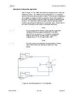
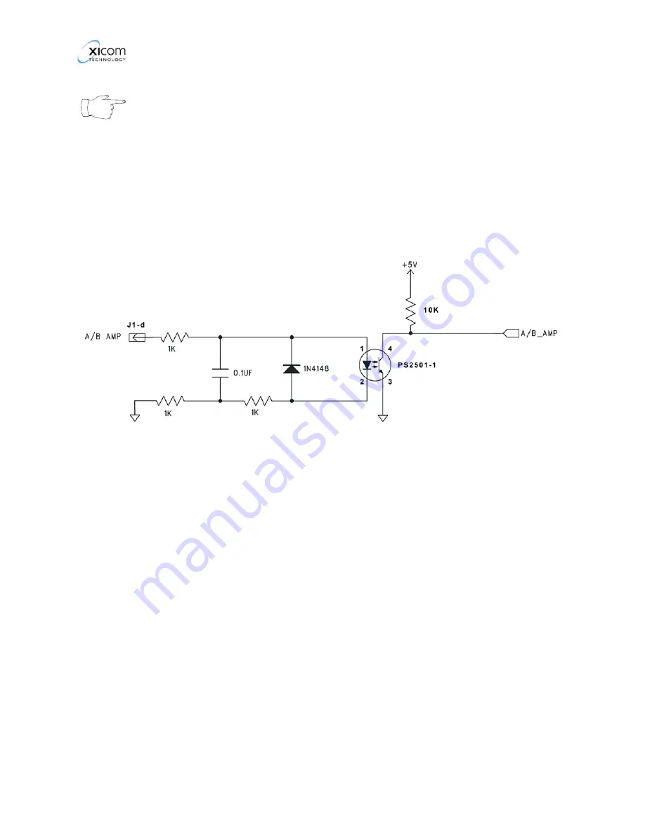
A/B AMP Select J1-d
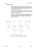
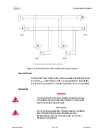
Refer to Figure 6. The Amplifier A/B select is an Opto isolator input.
When the input at J1-d is HI, amplifier address B is selected. Otherwise,
amplifier address A is selected.
Figure 6, A/B Amplifier select
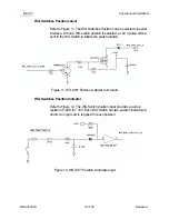
Re-program Computer J1-e
Connect this input low (to pin Z or a) to update firmware. To update
firmware, please refer to Firmware Update procedure MNC-0500-014 for
details.
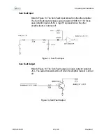
Summary Fault Dry Contact J1-S to J1-X
Two sets of Form C relay contacts (Summary Fault A and Summary Fault
B) are used to indicate that a fault has occurred.
The Summary Fault indicator signals change state any time an amplifier
fault occurs. The user has the choice of a normally open or normally
closed circuit.
Summary of Contents for XTS-200C
Page 10: ...MNC 0000 010 2 Revision A6...
Page 38: ...MNC 0200 004 14 of 14 Revision C Safety Sicherheit...
Page 64: ...MNC 0300 011 26 of 26 Revision H Unpacking and Installation...
Page 72: ...Operation MNC 0400 012 8 of 8 Revision C...
Page 104: ...MNC 0500 010 32 Revision D Solid State Power Amplifier Communication and Protocol...
Page 122: ...MNC 0700 001 6 Revision F Service and Repair...
Page 131: ......
Page 132: ......
Page 133: ......
Page 134: ......
Page 135: ......
Page 136: ......
Page 137: ......
Page 138: ......
Page 139: ......
Page 140: ......
Page 144: ...MNC 0000 039 4 of 12 Revision 2 ODU SSPA Power Supply Removal...
Page 152: ...MNC 0000 039 12 of 12 Revision 2 ODU SSPA Power Supply Removal...
Page 155: ...MNC 0000 003 3 of 4 Revision B Operation Addendum SSPA M C Termination Cable...
Page 156: ...MNC 0000 003 4 of 4 Revision B Operation Addendum SSPA M C Termination Cable...
Page 160: ...MNC 0000 002 4 Revision A Protocol Adendum Block Upconverter...