


CH32V003
Reference Manual
V1.3
121
-Counter overflow/underflow
-Setting the UG position
-Updates generated from the mode controller
1
UDIS
RW
Disable updates, the software allows/disables the
generation of UEV events via this bit.
1: UEV is disabled. no update event is generated and
the registers (ATRLR, PSC, CHCTLRx) maintain their
values. If the UG bitis set or a hardware reset is issued
from the mode controller, the counter and prescaler are
reinitialized.
0: UEV is allowed. update (UEV) events are generated
by any of the following events:
- Counter overflow/underflow
-Setting the UG position
-Updates generated from the mode controller registers
with caches are loaded with their preloaded values.
0
0
CEN
RW
Enable the counter (Counter enable).
1: Enables the counter.
0: Disable the counter.
Note: The external clock, gated mode and encoder
mode will not work until the CEN bit is set in software.
Trigger mode can automatically set the CEN bit in
hardware.
0
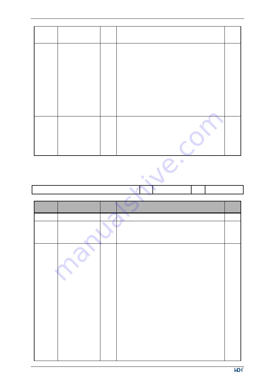
11.4.2 Control Register 2 (TIM2_CTLR2)
Offset address: 0x04
15
14
13
12
11
10
9
8
7
6
5
4
3
2
1
0
Reserved
TI1S
MMS[2:0]
CCDS
Reserved
Bit
Name
Access
Description
Reset
value
[15:8] Reserved
RO Reserved
0
7
TI1S
RW
TI1 selection.
1: TIMx_CH1, TIMx_CH2 and TIMx_CH3 pins
connected to TI1 input after heterodyning.
0: TIMx_CH1 pin is connected directly to TI1 input.
0
[6:4]
MMS
RW
Master mode selection: These 3 bits are used to select
the synchronization information (TRGO) sent to the
slave timer in master mode. The possible combinations
are as follows.
000: The Reset-UG bit is used as a trigger output
(TRGO). If the reset is generated by a trigger input
(from a mode controller in reset mode), there is a delay
in the signal on TRGO relative to the actual reset.
001: Enable - The counter enable signal CNT_EN is
used as a trigger output (TRGO). Sometimes it is
necessary to start multiple timers at the same time or to
control the enable from timers over a period of time.
The counter enable signal is generated by the logical or
of the trigger input signal in CEN control bit and gated
mode. When the counter enable signal is controlled by
a trigger input, there is a delay on TRGO unless
master/slave mode is selected (see the description of the
MSM bit in the TIMx_SMCFGR register).
010: The update event is selected as a trigger input
(TRGO). For example, the clock of a master timer may
be used as a prescaler for a slave timer.
0


