wc_tx001903gb.fm
51
E 1100
Operation
4.15
Powering Up the Machine
Requirements
Pre-starting checks completed
Generator started, if applicable
Procedure
Perform the procedure below to power up the machine.
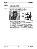
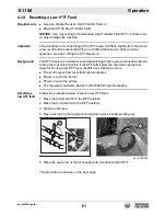
1. Move all switches and circuit breakers to the OFF position.
2. Move the genset circuit breaker
(b)
to the ON position.
3. Move the circuit breaker switch
(a)
to the ON position.
4. Check that the indicator light of the GFCI
(e)
is off. Press the “
RESET”
button of
the GFCI if its indicator light is ON.
5. Check that the low-level-fault indicator light
(c)
is OFF. If this light is ON, add
Heat Transfer Fluid (HTF) to the reservoir. See Topic
Filling the HTF Reservoir.
6. Check that the displays of the temperature controller
(d)
illuminate. If the
displays of the temperature controller do not illuminate, there is a problem with
GFCI or a problem with the wiring to the temperature controller. Disconnect the
main power supply and rectify the problem before continuing.
wc_gr008705
e
c
a
d
b
Summary of Contents for 5000620172
Page 19: ...E 1100 Safety Information wc_si000628gb fm 19 Notes ...
Page 20: ...Labels E 1100 20 wc_si000629gb fm 2 Labels 2 1 Label Locations wc_gr009588 ...
Page 105: ...ghi_tx001153gb fm 105 E 1100 Maintenance ...
Page 122: ...Technical Data E 1100 122 wc_td000476gb fm 10 5 Dimensions cm in wc_gr008706 ...
Page 133: ...wc_tx001673gb fm 133 Fuji Temperature Controller ...
Page 134: ...wc_tx001673gb fm 134 Fuji Temperature Controller ...
Page 151: ...E 1100 Schematics wc_tx001908gb fm 151 11 3 Burner System Circuit ...
Page 152: ...Schematics E 1100 152 wc_tx001908gb fm 11 4 Circulation System Circuit ghi_gr005662 ...
Page 153: ...E 1100 Schematics wc_tx001908gb fm 153 11 5 Rewind System Circuit ...
Page 158: ...Schematics E 1100 158 wc_tx001908gb fm 11 10 Genset DC Wiring Diagram ...
Page 160: ......
Page 161: ......


