wc_tx001903gb.fm
55
E 1100
Operation
4.19
Hose Spacing Guidelines
Background
When laying hose in the application area, the space between individual lines of
hose significantly affects the progress of the application. Although it is impossible
to predict the ambient conditions for each job site, Wacker Neuson recommends
observing the following guidelines to maximize efficiency.
Hose spacing
diagram
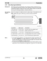
Refer to the diagram and table below when placing hoses in the application area.
Note:
Adjustments may be necessary to achieve maximum efficiency.
Notes
To increase heat penetration, cover the hoses with a plastic vapor barrier and
two layers of
Red Wave
™ insulated blankets. For concrete curing, cover the
concrete with plastic, place the hoses on top of the plastic, then cover the hoses
with two layers of
Red Wave
insulated blankets.
The hoses may be positioned vertically along concrete framing walls for curing
applications. Contact Wacker Neuson Application Support for more information.
Application
Distance (d)
Description
Frost prevention
91.5 cm (36 in.)
Prevents frost in the application area.
Concrete curing
61 cm (24 in.)
Allows concrete to cure.
Excavation thaw
61 cm (24 in.)
Partially thaws the ground for excavation.
Compaction thaw
45.7 cm (18 in.)
Completely thaws the ground for compaction.
Accelerated thaw
30.5 cm (12 in)
Up to 50% faster than compaction thaw.
Summary of Contents for 5000620172
Page 19: ...E 1100 Safety Information wc_si000628gb fm 19 Notes ...
Page 20: ...Labels E 1100 20 wc_si000629gb fm 2 Labels 2 1 Label Locations wc_gr009588 ...
Page 105: ...ghi_tx001153gb fm 105 E 1100 Maintenance ...
Page 122: ...Technical Data E 1100 122 wc_td000476gb fm 10 5 Dimensions cm in wc_gr008706 ...
Page 133: ...wc_tx001673gb fm 133 Fuji Temperature Controller ...
Page 134: ...wc_tx001673gb fm 134 Fuji Temperature Controller ...
Page 151: ...E 1100 Schematics wc_tx001908gb fm 151 11 3 Burner System Circuit ...
Page 152: ...Schematics E 1100 152 wc_tx001908gb fm 11 4 Circulation System Circuit ghi_gr005662 ...
Page 153: ...E 1100 Schematics wc_tx001908gb fm 153 11 5 Rewind System Circuit ...
Page 158: ...Schematics E 1100 158 wc_tx001908gb fm 11 10 Genset DC Wiring Diagram ...
Page 160: ......
Page 161: ......


