wc_tx001903gb.fm
44
Operation
E 1100
4.11
Positioning the Machine
CO Alarms
Because this machine produces carbon monoxide (CO), Wacker Neuson
recommends that CO alarms be installed in all structures in close proximity to the
machine. CO alarms provide an extra measure of protection against this poison
that you cannot see or smell.
Install battery-operated CO alarms or plug-in CO alarms with battery backup,
according to the manufacturer’s instructions. CO alarms should be certified to the
requirements of the latest safety standards (UL 2034, IAS 6-96, or CSA 6.19.01).
Test the CO alarm batteries monthly.
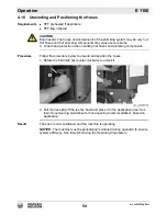
Requirements
Position the machine:
So that burner exhaust will not enter nearby structures.
So that the machine does not block traffic.
So that the machine is not close to any combustible material or flammable
vapor.
So that all of the machine’s access doors/panels may be accessed.
So that HTF hoses do not pose tripping hazards, and so the HTF hoses cannot
be damaged by machines or other equipment on the job site.
This procedure continues on the next page.
DANGER
Asphyxiation hazard.
Exhaust gas from the burner contains carbon monoxide, a deadly poison you
cannot see or smell. Exposure to carbon monoxide can kill you in minutes.
f
Position the machine so that burner exhaust will not enter any nearby struc-
tures.
WARNING
Fire hazard. Do not move the machine while it is running.
f
Shut down the machine before moving or repositioning it.
WARNING
Fire hazard. Machines positioned on a hill or an incline may slide, break away or
roll over.
f
Do not position the machine on a hill or an incline.
WARNING
Explosion and fire hazard. Risk of severe injury or death.
f
Do not operate the machine near flammable vapors, fuels, or combustibles.
Summary of Contents for 5000620172
Page 19: ...E 1100 Safety Information wc_si000628gb fm 19 Notes ...
Page 20: ...Labels E 1100 20 wc_si000629gb fm 2 Labels 2 1 Label Locations wc_gr009588 ...
Page 105: ...ghi_tx001153gb fm 105 E 1100 Maintenance ...
Page 122: ...Technical Data E 1100 122 wc_td000476gb fm 10 5 Dimensions cm in wc_gr008706 ...
Page 133: ...wc_tx001673gb fm 133 Fuji Temperature Controller ...
Page 134: ...wc_tx001673gb fm 134 Fuji Temperature Controller ...
Page 151: ...E 1100 Schematics wc_tx001908gb fm 151 11 3 Burner System Circuit ...
Page 152: ...Schematics E 1100 152 wc_tx001908gb fm 11 4 Circulation System Circuit ghi_gr005662 ...
Page 153: ...E 1100 Schematics wc_tx001908gb fm 153 11 5 Rewind System Circuit ...
Page 158: ...Schematics E 1100 158 wc_tx001908gb fm 11 10 Genset DC Wiring Diagram ...
Page 160: ......
Page 161: ......


