wc_tx001903gb.fm
40
Operation
E 1100
4.6
General Sequence of Operation
Follow the sequence of operation below. Refer to the specific topic for details.
Task
When/Where
See Topic
1. Check HTF level.
Before leaving for the job site.
Or, when at the job site before
daily operation.
4.5
2. Check fuel level.
4.6 / 4.7
3. Position the machine.
At the job site.
4.9
4. Start the genset engine.
OR
4. Connect power.
4.12
4.13
5. Perform pre-starting checks.
4.11
6. Power up the machine.
4.14
7. Run the machine.
—
a. Preheat the HTF (if necessary).
4.16
b. Initiate HTF flow.
4.17
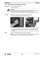
c. Unwind and position the hoses.
4.19 / 4.20
d. Monitor the operating parameters.
4.21
e. Adjust the burner (if necessary).
Burner
Setup
8. Rewind the hoses
4.22
9. Shut down and pack up the machine.
4.23
Summary of Contents for 5000620172
Page 19: ...E 1100 Safety Information wc_si000628gb fm 19 Notes ...
Page 20: ...Labels E 1100 20 wc_si000629gb fm 2 Labels 2 1 Label Locations wc_gr009588 ...
Page 105: ...ghi_tx001153gb fm 105 E 1100 Maintenance ...
Page 122: ...Technical Data E 1100 122 wc_td000476gb fm 10 5 Dimensions cm in wc_gr008706 ...
Page 133: ...wc_tx001673gb fm 133 Fuji Temperature Controller ...
Page 134: ...wc_tx001673gb fm 134 Fuji Temperature Controller ...
Page 151: ...E 1100 Schematics wc_tx001908gb fm 151 11 3 Burner System Circuit ...
Page 152: ...Schematics E 1100 152 wc_tx001908gb fm 11 4 Circulation System Circuit ghi_gr005662 ...
Page 153: ...E 1100 Schematics wc_tx001908gb fm 153 11 5 Rewind System Circuit ...
Page 158: ...Schematics E 1100 158 wc_tx001908gb fm 11 10 Genset DC Wiring Diagram ...
Page 160: ......
Page 161: ......


