ADVANCED FUNCTIONS AND OPERATIONS : Setting the STEP PASS
6-56
6.29 Setting the STEP PASS
This function is used in cases where the distance between the coordinate points of
cutting data is extremely short. Because the cutting data will be processed in units
specified by the STEP PASS setting, better image quality is gained as a result of
stable rotation of the cutter blade’s tip.
S
ETTING
P
ROCEDURE
1
Press the
MENU
key.
2
Press the
NEXT
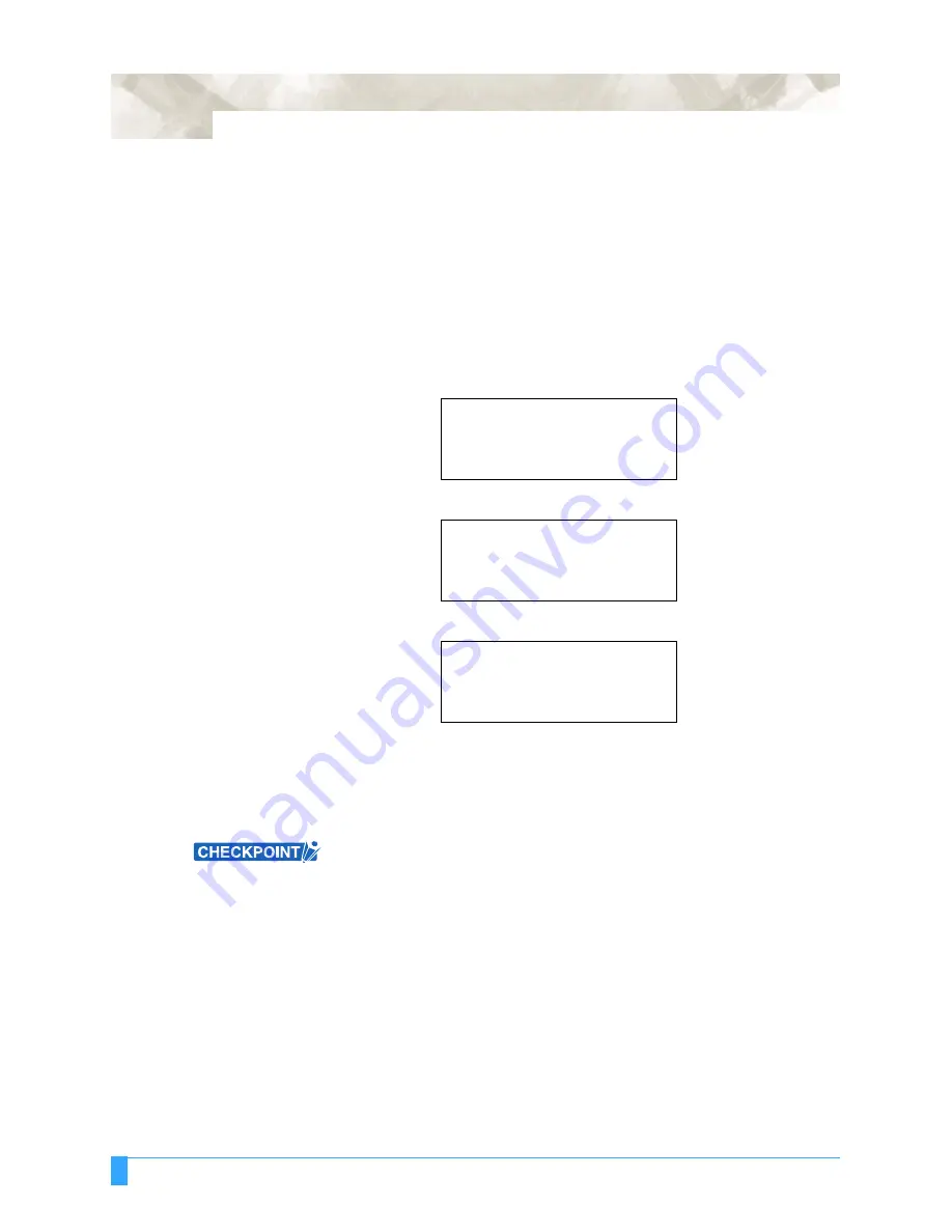
key until the following menu appears.
3
Press the
F3
key (OPTION 1). The following menu appears.
4
Press the
F4
key (STEP PASS). The following menu appears.
5
Use the (
▲▼
)
POSITION
keys to increase or decrease the value in the range
from 0 to 20.
6
Press the
ENTER
key to register your setting.
7
Press the
MENU
key to return the plotter to Ready status.
• This setting is retained in the plotter’s internal memory even when the power is
turned off.
•
If the STEP PASS setting is too high, the image cut may not be faithfully
reproduced. Normally, the STEP PASS setting should be set to “0.”
PEN UP/DOWN>
BACKGROUND SETTINGS>
OPTION 1>
OPTION 2>
PEN UP SPEED>
OFFSET ANGLE>
OFFSET FORCE>
STEP PASS>
STEP PASS
STEP PASS = 0
Summary of Contents for Q100
Page 34: ...Cutter Blades and Cutter Pens Adjusting the Blade Length 2 6 ...
Page 64: ...Pen Setting Conditions Adjusting the Blade Length 4 12 ...
Page 140: ...ADVANCED FUNCTIONS AND OPERATIONS Selecting the Type of Perforated Line 6 62 ...
Page 148: ...OPTIONS Pen Offset for 2 pen models only 7 8 ...
Page 174: ...INTERFACES COMMAND Settings 10 8 ...


