DOC: 03-925702-01
DESC:
Assy, 3800GC Keyboard/Button-up
PAGE:
REV
3 of 6
3
PREPARED BY: Sax Makthepharack REVISED BY:
CONTROL: INDUSTRIAL ENGINEERING
REV. DATE:
SHOWN
-
01 - 19 - 00
Michael Slaughter
1.
3800GC KEYBOARD/BUTTON-UP, ASSEMBLY PROCEDURES
1.1
KEYBOARD HOUSING ASSEMBLY
1.1.1
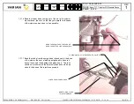
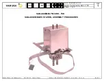
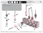
Feed Keyboard Overlay (03-925277-01) connector through slotted hole on Keyboard Housing Display (03-925207-01), using two 4-40 x 7/16 Hex Standoffs
(22-431139-00) and four 4-40 Keps Nuts (13-312004-00) secure in place as shown. Finger tighten only.
1.1.2
Remove adhesive backing paper from Menu Label and apply into indented part on Keyboard Housing Display where shown.
1.1.3
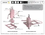
Place Keyboard Housing Display face down and install PWA Front Panel (03-925800-01), using three 6-32 x 3/8 Sems Ext. Screws (12-901134-00) as shown.
1.1.4
Install Ground Strip Left (03-925275-00), using one 6-32 x 3/8 Sems Ext. Screw (12-901134-00), one 8-32 x 3/8 Sems Ext. Screw (12-901163-00) and one
4-40 x 1/4 Pan Screw (12-222004-02) with #4 Ext. Lock Washer (14-312004-00) as shown.
1.1.5
Repeat previous Step 1.1.4 for Ground Strip Right (03-925276-00) on opposite side.
1.1.6
Install LCD Display (03-925359-01), using four 2-56 x 1/4 Pan Screws (12-222002-04) and leave the screws loose.
1.1.7
Connect the connector from the Keyboard Overlay to
(J-101)
and connect connector from LCD Display to
(J-102)
on PWA Front Panel.
1.2
ADJUSTMENT AND TEST
1.2.1
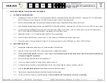
Assemble the keyboard and display, leave all 11 screws installed but not tightened.
1.2.2
Adjust R2, contrast control on the bottom of the display housing to approximately mid point.
1.2.3
With the
power off (red light off),
install the unit on the alignment fixture.
Make sure the hold down clamp does not run into the two black twisted wires
or the power supply PS1 on the board.
1.1.4
Plug in the flat ribbon cable with the red wire toward the left.
1.1.5
Turn on the main power switch. The display takes a moment to come on.
1.1.6
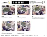
Looking directly over the center of the keyboard/display into the mirror carefully align the display as described in figure #1.
1.1.7
Using the
insulated plastic prying tool
align the display as shown in attached photos.
1.1.8
Tighten only two diagonally positioned screws when alignment seems complete.
1.1.9
Turn the main power off to tighten the remaining screws.
If your screwdriver slips it could destroy the fixture or the display.


