160
03-914648-00:7
Notice how the Ethernet cables (shown by the heavy black line) along with
the BNC Tees provide a single unbroken path from one BNC terminator to
the other.
More detailed information on setting up Star Workstation communications is
provided in the Star 3800 GC Control Software Installation and Operation
manual. Ethernet communication troubleshooting information is provided in
the troubleshooting section of the same manual.
Analog Communications
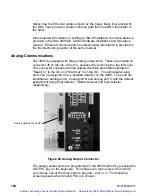
The 3800 is equipped with three analog output ports. These are located on
connector J6 on the top of the GC, accessed by removing the top left cover.
This connector contains all three analog channels plus status signals for
“Ready In” to the GC and “Start Out” from the GC. The individual analog
ports can be assigned to any installed detector on the 3800. The ports are
identified as analog port A, analog port B and analog port C with the default
assignment being front detector, middle detector and rear detector
respectively.
Figure 28 Analog Output Connector
The analog output ports are programmed in the 3800 method by pressing the
OUTPUT key on the keyboard. This brings up a menu screen from which
you choose one of the three ports to program; A, B or C. The following
screen appears when Analog Port A is chosen.
Analog Output Connector
Artisan Technology Group - Quality Instrumentation ... Guaranteed | (888) 88-SOURCE | www.artisantg.com

