112
03-914648-00:7
6
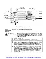
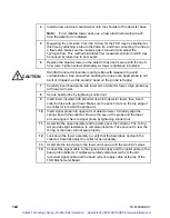
Carefully insert the ignitor probe into the lower arm of the detector tower.
Align the probe key with the tower arm slot
.
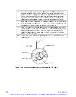
Check the orientation of the
ignitor elements by looking down through the top of the detector tower. The
spring clip should slip around the flame tip and make good contact (see
Figure 14). The ignitor coil must not touch the flame tip assembly nor be
positioned directly above it. Tighten the knurled nut to secure the probe.
7
Make sure the notch in the detector tower arm does not cut the O-ring seal.
8
Insert the insulator into the detector tower, then insert the collector tube into
the tower. The collector tube must not touch the ignitor coil.
9
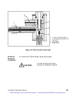
Insert the signal probe into the upper arm of the detector tower. The probe
clip should fit around the tapered section on the collector tube tightly enough
to exert a downward force (see Figure 15 ). Secure the signal probe by
tightening the knurled nut. Make sure the notch in the detector tower arm
does not cut the o-ring seal.
10
Connect the ignitor cable to the ignitor probe and the signal cable to the
signal probe.
Figure 14 Orientation of Ignitor Probe Elements in FID Tower
Detector Tower
Spring Clip
Ignitor Coil
TOP VIEW
Flame Tip
Artisan Technology Group - Quality Instrumentation ... Guaranteed | (888) 88-SOURCE | www.artisantg.com

