background image

Addendum

A.32

Manual Page Number

Revision

 70–83 

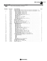
Parts, Electrical Enclosure Assembly 

(continued)

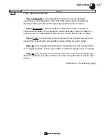
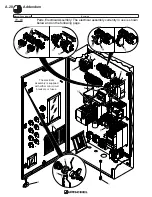
: The enclosure assembly 

door parts currently in use are shown below and on the following page.

Summary of Contents for COMITROL 2100

Page 1: ...Instruction Manual SAFETY GENERAL INFORMATION INSTALLATION OPERATION MAINTENANCE PARTS LABORATORIES INCORPORATED COMITROL PROCESSOR MODEL 2100...

Page 2: ......

Page 3: ...her inquiries info urschel com 7 Safety Rules for Safe Operation Add the following Lockout Procedure m WARNING Always follow the lockout procedure before opening any guard Failure to lock out the powe...

Page 4: ...monitored by a safety relay which shuts down the machine if the button fails 13 14 Safety Safety Switch System A safety monitor 2 is supplied with the current electrical system See the entries for pag...

Page 5: ...e frequency drive VFD is used to control the speed of the feed screw motor 1 Feed screw speed is controlled by a potentiometer 2 located on the front of the electrical enclosure 22 General Information...

Page 6: ...y stop button 4 was previously pushed it must be reset rotate and pull out to reset 3 Turn the disconnect switch handle on I 4 Press the impeller start button 5 The pilot light 6 will illuminate when...

Page 7: ...product remaining in the machine 3 Push the impeller stop button 3 The impeller motor will stop 4 Turn the disconnect switch handle off O Lock out the handle with the padlock or in accordance with you...

Page 8: ...starting and stopping procedures for the current electrical system The top reset button is labeled MASTER RESET 1 If the emergency stop button 2 was previously pushed the button must be reset in order...

Page 9: ...ing will also cause premature damage and failure of machine components The potentiometer dial 1 on the electrical enclosure controls the speed of the feed screw motor To increase the feed rate turn th...

Page 10: ...f the overload before the machine is restarted If the machine stops check the yellow motor overload light 1 on the outside of the electrical enclosure The light will illuminate if the impeller motor f...

Page 11: ...ribed in the manual Refer to the variable frequency drive manufacturer s manual for the procedure when the digital operator displays a different error code If the impeller or agitator motors have over...

Page 12: ...ain circuit breaker with disconnect switch 3 The machine is supplied with a soft start controller 4 The soft start controls the inrush of current to the impeller motor when the impeller start button i...

Page 13: ...and new machines were supplied with a safety monitor 2 beginning in 2018 The monitor serves a function similar to that of the amplifier but is not a direct replacement and is not interchangeable See...

Page 14: ...osed for the machine to run When a guard is removed the corresponding status light turns red Remove the cutting enclosure for example see Maintenance Covers and Guards in the machine manual with the d...

Page 15: ...H1 4 CH2 5 K1 6 K2 The Power CH1 CH2 K1 and K2 LEDs are lit All guards are in place and the emergency stop button is reset The machine is ready to start The Power and Reset LEDs are lit A guard s has...

Page 16: ...efer to the setting on the old breaker or see the Current Transformer Windings Chart included in this addendum A small section of the chart 4 is shown at the right See the column in the chart titled m...

Page 17: ...ce up 4 Wind the primary wire through the transformer Refer to your notes from Step 1 or see the Current Transformer Windings Chart included in this addendum A small section of the chart 6 is shown at...

Page 18: ...s through the current transformer 3 Start the machine and measure the amperage 3 Divide the measured amperage by the motor full load amperage full load amperage is found on the motor name plate Multip...

Page 19: ...l the fasteners that secure the indicator to the bracket 4 Locate the wire that is wound through the current transformer 2 Connect this wire to the positive terminal on the back of the indicator Conne...

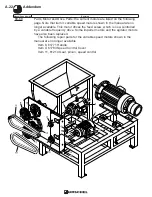
Page 20: ...Addendum A 18 58 59 Parts Frame Assembly the current frame and related parts are shown below Manual Page Number Revision 61453 Frame Assembly 364 Frame Motor...

Page 21: ...Screw 3 8 16 x 1 3 4 s s 4 10 10249 Hex Nut 3 8 16 s s locking thick 4 61643 Belt Guard Assembly includes items 11 21 1 11 61640 Belt Guard back 1 12 61642 Belt Guard ring 1 13 61401 Belt Guard inner...

Page 22: ...Addendum A 20 Manual Page Number Revision 60 61 Parts Agitator Feed Screw the current agitator feed screw and related parts are shown below...

Page 23: ...Reducer Mount feed screw 1 15 10321 Hex Nut 1 2 13 s s locking 5 16 61765 Shaft feed screw drive 1 17 61769 Key 1 2 x 3 8 x 2 1 18 61768 Reducer 1 19 10058 Hex Head Cap Screw 3 8 16 x 1 s s 4 20 10015...

Page 24: ...le This motor drives the feed screw which is now controlled by a variable frequency drive Some impeller motors and the agitator motors have also been replaced The following repair parts for the variab...

Page 25: ...6 10270 Washer flat 3 8 s s thick 4 7 10249 Hex Nut 3 8 16 s s locking thick 4 8 12221 Pulley V 3 25 O D 875 I D 2 groove w set screw 1 9 61602 Pulley V 8 25 O D 938 I D 2 groove w set screw 1 10 122...

Page 26: ...69 Parts Motor and Drive Parts Motor Brake Horizontal Stearns 87000 REV B See the picture below and the parts list on the following page for the current brake assemblies and related parts Manual Page...

Page 27: ...Coil Kit 460 volts 87000 6 CL B for machines sold 2018 and later with soft start 1 63694 Solenoid Coil Kit 400 volts 50 60 HZ 1 63688 Solenoid Coil 200 240 volts 50 60HZ for machines sold prior to 20...

Page 28: ...Addendum A 26 This page intentionally left blank...

Page 29: ...evious motor circuit protective devices and current transformer windings Pages 70 83 in the manual contain repair parts for discontinued electrical assemblies Repair parts are available unless otherwi...

Page 30: ...ual Page Number Revision 70 83 Parts Electrical Assembly The electrical assembly currently in use is shown below and on the following page The electrical assembly is supplied with either mini circuit...

Page 31: ...ssemblies also include the Safety Sensors and Enclosure Fittings See the following pages The Electrical Schematic VFD Chart and Soft Start Chart are illustrated on the following pages Control Circuit...

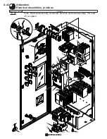
Page 32: ...umber Revision 70 83 Parts Electrical Enclosure Assembly The electrical enclosure assembly currently in use is shown below and on the following page The electrical assembly is supplied with either min...

Page 33: ...Safety Relay SCR 31 i Viper SR1 22 1 21545 Control Relay 3 normally open 1 normally closed 24 volt CR4 23 1 21934 Control Relay Socket mini 4 changeover contacts CR1 24 1 21935 Control Relay mini 4 f...

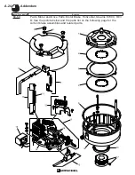
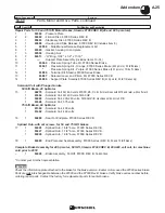
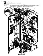
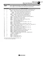
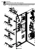
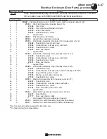
Page 34: ...Addendum A 32 Manual Page Number Revision 70 83 Parts Electrical Enclosure Assembly continued The enclosure assembly door parts currently in use are shown below and on the following page...

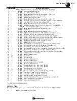
Page 35: ...905 Legend Plate impeller stop 19 1 21867 Legend Plate feed screw stop 20 1 21907 Legend Plate agitator stop 1 21622 Push Button Assembly reset includes items 21 24 21 1 21623 Push Button reset 22 1 2...

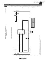
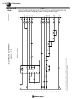
Page 36: ...Addendum A 34 Manual Page Number Revision 70 83 Parts Electrical Schematic 64272 Use with the electrical assembly and electrical enclosure assembly shown on the previous pages...

Page 37: ...A 35 Addendum Manual Page Number Revision 70 83 Parts Electrical Schematic 64272 Use with the electrical assembly and electrical enclosure assembly shown on the previous pages...

Page 38: ...Addendum A 36 Manual Page Number Revision 70 83 Parts Electrical Schematic 64272 Use with the electrical assembly and electrical enclosure assembly shown on the previous pages...

Page 39: ...A 37 Addendum Manual Page Number Revision 70 83 Parts Electrical Schematic 64272 Use with the electrical assembly and electrical enclosure assembly shown on the previous pages...

Page 40: ...Addendum A 38 Manual Page Number Revision 70 83 Parts VFD Chart and Soft Start Chart 64273 Use with the electrical assembly shown on the previous pages...

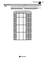
Page 41: ...62 2 7 63 2 8 64 2 8 65 2 9 66 2 9 67 2 10 68 1 9 69 1 9 70 1 9 71 200 A 21802 5 1 9 72 1 8 73 1 8 74 1 8 75 1 7 76 1 7 77 1 7 78 1 7 79 1 6 80 1 6 70 83 Parts Current Transformer Windings Chart Use...

Page 42: ...on 70 83 Parts Electrical Assembly Safety Sensors and Enclosure Fittings The safety sensors and enclosure fittings currently in use are shown below and on the following page Agitator Motor Sensor 1 Se...

Page 43: ...1 9 32 15 4 11611 Lock Nut 1 2 16 1 11540 Reducing Bushing 1 1 2 x 2 17 1 11619 Conduit Connector straight 1 1 2 18 2 11964 Cord Connector 90 degree 500 625 19 1 21461 Cord Connector 45 degree 1 1 2...

Page 44: ...Manual Page Number Revision A 42 Addendum Electrical Assemblies previous 70 83 Parts Electrical Assembly continued previous electrical assembly Y D start CE compliant...

Page 45: ...rence only See chart 1 below See chart 2 below Electrical assemblies also include the Safety Switches and Enclosure Fittings see the following pages Motor Full Load Amperage Overload Relay Part Number...

Page 46: ...dendum Electrical Enclosure previous 70 83 Parts Electrical Assembly continued previous electrical enclosure Y D start CE compliant use with 64094 and 64095 electrical assemblies Manual Page Number Re...

Page 47: ...Machine Screw with washer 10 32 x 1 2 14 1 63385 Current Transformer 15 4 10625 Round Head Machine Screw with washer 10 32 x 1 2 16 1 21525 Variable Frequency Drive 460 volt 9 2 amps VFD includes item...

Page 48: ...m Electrical Enclosure Door Parts previous 70 83 Parts Electrical Assembly continued previous electrical enclosure Y D start CE compliant use with 64094 and 64095 electrical assemblies Manual Page Num...

Page 49: ...27 Push Button stop 20 1 21714 Contact Block normally closed self monitoring with latch 21 1 21428 Legend Plate yellow round 22 1 21578 Washer push button anti rotation 23 1 21572 Push Button Nut meta...

Page 50: ...A 48 Addendum Electrical Schematic 64096 70 83 Parts Electrical Assembly continued previous electrical schematic for 64094 and 64095 electrical assemblies Manual Page Number Revision...

Page 51: ...A 49 Addendum Electrical Schematic Drive Constants 70 83 Parts Electrical Assembly continued previous drive constants use with 64096 schematic Manual Page Number Revision...

Page 52: ...A 50 Addendum Electrical Assembly previous 70 83 Parts Electrical Assembly continued previous electrical assemblies across the line start Manual Page Number Revision...

Page 53: ...r supplied for reference only See chart 1 below See Electrical Schematic Drive Constants and Overload Relay Charts on the following pages See chart 2 below See chart 3 below Electrical assemblies also...

Page 54: ...m Electrical Enclosure previous 70 83 Parts Electrical Assembly continued previous electrical enclosure across the line start use with 64099 64100 64098 and 64097 electrical assemblies Manual Page Num...

Page 55: ...r Bracket 11 4 10625 Round Head Machine Screw with washer 10 32 x 1 2 12 1 63385 Current Transformer 13 4 10625 Round Head Machine Screw with washer 10 32 x 1 2 14 6 21349 Fuse Base 30 amp cube for FU...

Page 56: ...Electrical Enclosure Door Parts Manual Page Number Revision 70 83 Parts Electrical Assembly continued previous electrical enclosure across the line start use with 64099 64100 64098 and 64097 electric...

Page 57: ...1 21427 Push Button stop 20 1 21714 Contact Block normally closed self monitoring with latch 21 1 21428 Legend Plate yellow round 22 1 21578 Washer push button anti rotation 23 1 21572 Push Button Nut...

Page 58: ...A 56 Addendum Electrical Schematic 64101 70 83 Parts Electrical Assembly continued previous electrical schematic for 64099 64100 64098 and 64097 electrical assemblies Manual Page Number Revision...

Page 59: ...CT Winding PRI SEC 60 12838 2 6 61 12838 2 7 62 12838 2 7 63 12838 2 8 64 12839 2 8 65 12839 2 9 66 12839 2 9 67 12839 2 10 68 12839 2 9 Chart 1 40 hp Motor 460V FLA Overload Relay CT Winding PRI SEC...

Page 60: ...losure Fittings Switch Number 1 Feed Screw Motor Impeller Motor Agitator Motor Switch Number 2 70 83 Parts Electrical Assembly continued safety switch and enclosure fittings for previous electrical as...

Page 61: ...9 32 16 1 11611 Lock Nut 1 2 17 4 11614 Conduit Connector 90 degree 1 2 18 1 11613 Conduit Connector straight 1 2 60 hp machines only used at feed screw motor 19 2 11502 Reducing Bushing 1 2 x 3 4 20...

Page 62: ...dendum Repair Parts for Previous Electrical Assembly and Enclosure A 60 Manual Page Number Revision 70 83 Parts Electrical Assembly continued repair parts for previous electrical assembly and enclosur...

Page 63: ...21349 Fuse Base 30 amp cube FU1 FU2 6 28 12930 Modular Fuse Holder 2 pole FU3 1 29 12763 Fuse Terminal 5 x 20 mm IEC includes item 30 1 30 12781 Transparent Cover 1 31 12753 Contactor 22 A IEC include...

Page 64: ...dendum Repair Parts for Previous Electrical Assembly and Enclosure A 62 Manual Page Number Revision 70 83 Parts Electrical Assembly continued repair parts for previous electrical assembly and enclosur...

Page 65: ...replace items 57 and 58 with 21433 assy 1 58 Discontinued replace items 57 and 58 with 21433 assy 1 59 49637 Potentiometer 2500 ohms 1 60 49638 Legend Plate graduated markings 1 61 12747 Reset Button...

Page 66: ...endum Repair Parts for Previous Electrical Assemblies and Enclosure A 64 Manual Page Number Revision 70 83 Parts Electrical Assembly continued repair parts for previous electrical assembly and enclosu...

Page 67: ...1 22 12871 Transparent Cover For Adjustment Dial 1 23 51475 Control Circuit Transformer 150 VA 1 24 61443 Electrical Enclosure 140 amp includes items 25 66 1 25 12750 Earthing Terminal IEC 4 26 12760...

Page 68: ...dendum Repair Parts for Previous Electrical Assembly and Enclosure A 66 Manual Page Number Revision 70 83 Parts Electrical Assembly continued repair parts for previous electrical assembly and enclosur...

Page 69: ...1 55 21335 Pilot Light Assembly green includes items 56 57 1 56 21336 Pilot Light replacement LED green 1 57 21337 Pilot Light replacement Lens green 1 58 49637 Potentiometer 2500 ohms 1 59 49638 Leg...

Page 70: ...endum Repair Parts for Previous Electrical Assemblies and Enclosure A 68 Manual Page Number Revision 70 83 Parts Electrical Assembly continued repair parts for previous electrical assembly and enclosu...

Page 71: ...rthing Terminal IEC 4 27 12760 Terminal IEC 3 28 12751 End Anchor IEC 10 29 21349 Fuse Base 30 amp cube FU1 FU2 6 30 12930 Modular Fuse Holder 2 pole FU3 1 31 12763 Fuse Terminal 5 x 20 mm IEC include...

Page 72: ...endum Repair Parts for Previous Electrical Assemblies and Enclosure A 70 Manual Page Number Revision 70 83 Parts Electrical Assembly continued repair parts for previous electrical assembly and enclosu...

Page 73: ...1 58 21335 Pilot Light Assembly green includes items 59 60 1 59 21336 Pilot Light replacement LED green 1 60 21337 Pilot Light replacement Lens green 1 61 49637 Potentiometer 2500 ohms 1 62 49638 Leg...

Page 74: ...ndum Schematic for 61446 61448 61449 and 64445 Electrical Assemblies A 72 Manual Page Number Revision 70 83 Parts Electrical Assembly continued repair parts for previous electrical assembly and enclos...

Page 75: ...A 73 Addendum Schematic for 61476 and 61477 Electrical Assemblies Manual Page Number Revision 70 83 Parts Electrical Assembly continued repair parts for previous electrical assembly and enclosure...

Page 76: ...r and the schematic inside the electrical enclosure Motor Full Load Amps M2 M3 Fuse FU1 FU2 Cube Type Part No Amps 2 50 3 99 21341 6 4 00 5 49 21339 10 5 50 7 99 21339 10 8 00 8 57 21325 15 8 58 10 00...

Page 77: ...4 Starter Part No Description 90 63374 W76 91 63374 W76 92 63374 W76 93 63374 W76 94 63374 W76 95 63374 W76 96 63374 W76 97 63374 W76 98 63374 W76 99 63375 W77 100 63375 W77 101 63375 W77 102 63375 W...

Page 78: ...h DU 11718 11717 11719 11720 11721 Estonian ES 98165 98168 98167 98169 Finnish FI 11760 11759 11761 11762 11763 French F 11676 11675 11677 11678 11679 German GE 11683 11682 11684 11685 11686 Greek GR...

Page 79: ...egarding the safe operation of this machine contact Urschel Laboratories COPYRIGHT 2005 Urschel Laboratories Inc Valparaiso Indiana All rights reserved No part of this manual may be reproduced or tran...

Page 80: ...other safety messages in this manual and on the machine Recognize the safety alert symbol which indicates a potential personal safety hazard 2 Never work beyond defined safety skills 3 Insist on thor...

Page 81: ...S 20 Sizes of Cuts Cutting Head Description 20 Types of Cutting Head 21 IMPELLERS OPERATING SPEEDS AND SPEED CONTROL 22 Impellers Operating Speeds and Speed Control 22 INSTALLATION 23 SHIPMENT PRE INS...

Page 82: ...ifying Cutting Heads Inspection 44 Resharpening Cutting Heads 45 ELECTRICAL ASSEMBLY 46 Inspection 46 TROUBLESHOOTING 50 PARTS 53 ORDERING INFORMATION 55 Ordering Parts Returning Parts for Repair 55 T...

Page 83: ...NING Any person who oper ates cleans repairs adjusts installs or supervises the operation of or uses this machine in any way must know and follow all safety rules and operating principles set forth in...

Page 84: ...6 This page intentionally left blank...

Page 85: ...ust operate repair or maintain the machine Proper cleaning and maintenance proce dures are found in the maintenance section of this manual 7 This machine contains protective covers and guards equipped...

Page 86: ...harge chute 11666 PRECAUCION PRECAUCION CAUTION CAUTION MACHINE CONTAINS ROTATING PARTS SUCH AS SHARP KNIVES PULLEYS BELTS OR GEARS NEVER RUN MACHINE WITH ANY GUARD OR COVER REMOVED EVEN FOR CLEANING...

Page 87: ...LOCAR EL PROTECTOR O CUBIERTA DANGER PELIGRO Danger labels Figure 4 are visible when a protective cover or guard has been opened or removed This label warns you that the machine is unguarded and must...

Page 88: ...safety switches Always push the O STOP button then disconnect and lock out the power source When machine has come to a complete stop push the I IMPELLER START button to verify that the machine will no...

Page 89: ...he machine with a cover or guard opened removed or modi fied Serious personal injury may occur Covers and guards safety signs safety switches and brake motors are standard equipment on newly manufactu...

Page 90: ...m if the machine can be started while any cover or guard that is equipped with a safety switch is opened or removed DO NOT operate the machine in this condition Serious injury such as amputation could...

Page 91: ...red relay condition LEDs are illuminated a safety switch circuit is open When the red switch output LEDs are illuminated they indicate which correspon ding safety switch is open When the red attentio...

Page 92: ...chine has come to a complete stop WARNING Be careful to avoid contact with cutting parts and sharp edges exposed during the safety switch system test Contact with cutting parts and sharp edges could r...

Page 93: ...B W R 4 O B W R 3 O B W R O B W R O R2 R1 L2 L1 R W B 1 1 2 3 6 8 4 5 7 Figure 11 Amplifier and safety switches with corresponding covers and guards 1 Cutting Enclosure 2 Feed Adapter 3 Amplifier 4 Gr...

Page 94: ...16 This page intentionally left blank...

Page 95: ...17 GENERAL INFORMATION...

Page 96: ...pered to approxi mately 27 35 F 2 8 1 7 C For best results fresh and cooked meat should be tempered to approximately 35 40 1 7 4 4 C PRODUCTS WHICH ARE EXPLOSIVE or create a potentially explosive atmo...

Page 97: ...ed horizontal separators Small portions of product projecting into the spaces between the separators are cut off into parti cles by spaced columns of vertical knives These particles fly outward and aw...

Page 98: ...number indicates the height of the head 3 the pattern and number of columns the openings between and thickness of horizontal separators and the material of construction See page 44 for more detailed...

Page 99: ...available in the following types K 28 column type cutting heads are the most popular and are capable of cutting many kinds of product J 20 column type cutting heads have fewer columns than K type and...

Page 100: ...of noise levels use adequate ear protection OPERATING SPEEDS For optimum cutting results different products may require a change in feed screw speed Fresh and cooked meats require higher speeds while...

Page 101: ...23 INSTALLATION...

Page 102: ...for cleaning and maintenance The location should provide level footing adequate lighting and venti lation and provisions for excessive noise levels Never locate machine in an area with a potentially e...

Page 103: ...ents that have failed due to water or chemical contamination will not be cov ered under the warranty 2 Connect grounding conductor green or green and yellow striped wire to the earth termination point...

Page 104: ...26 This page intentionally left blank...

Page 105: ...ing or removing any cover or guard always turn the power disconnect lockout switch to O OFF and lock out power source After machine has come to a complete stop press the I IMPELLER START button to ver...

Page 106: ...ck the power disconnect lockout switch 5 Turn the power disconnect lockout switch to I ON Only the green relay condition LEDs on the amplifier should be lit 6 Press the top reset button The reset butt...

Page 107: ...source After the motor has come to a complete stop push the IMPELLER START button to verify that the machine will not start To stop the agitator only when the machine is running press the AGITATOR STO...

Page 108: ...into the electrical system The optimum feed rate may or may not be achieved at 100 motor load This will vary with the type of reduction head and product being run Once the feed rate has been establish...

Page 109: ...ing parts which could cause severe injury such as amputation 1 Push O STOP button then disconnect and lock out power source 2 Only qualified trained personnel should proceed to step 3 3 Visually verif...

Page 110: ...32 This page intentionally left blank...

Page 111: ...this machine Before opening or removing any cover or guard always turn the power discon nect lockout switch to O OFF and lock out power source After machine has come to a complete stop press the I IMP...

Page 112: ...Guard Cover and Back Remove to service speed reducers and belts Cutting Enclosure Remove to service cutting parts Impeller Hub Guard Remove to service hub and seal INSPECTION Inspect all covers and g...

Page 113: ...35 MAINTENANCE Covers and Guards Figure 22 Covers and guards 1 Belt Guard Cover 2 Belt Guard Back 3 Cutting Enclosure 4 Impeller Hub Guard between motor and cutting enclosure 3 4 2 1...

Page 114: ...e may chemically harm or destroy these and other materials Solutions containing chlo rine or acids can also be harmful Failure to completely remove these chemicals with an appropriate rinse will cause...

Page 115: ...ot have these signs or if they are no longer legible do not use the machine Install or replace the signs immediately INSPECTION Safety signs Inspect all safety signs on machine for damage Damaged loos...

Page 116: ...E No 26 Hydraulic Oil or equivalent See reduction unit manufac turer s instructions for additional specifica tions After an initial run of approximately 250 hours the housings should be drained prefer...

Page 117: ...er s instructions which are supplied with this machine NOTE With the machine running the variable speed motor should be cranked through the full range of speeds daily to keep internal parts lubricated...

Page 118: ...lear of feed screw Figure 26 MAINTENANCE Cutting and Feed Assemblies Figure 25 Cutting and Feed Assemblies 1 O Ring 2 Feed Adapter 3 Bearing 4 Feed Screw 5 Cutting Enclosure Backplate 6 Thrust Bearing...

Page 119: ...Figure 28 6 Remove seal cover and seal behind impeller see Figure 25 page 40 7 Remove impeller hub guard located behind cutting enclosure backplate to aid in cleaning and inspection of the area behin...

Page 120: ...ler Clean and inspect for damage or wear When impeller inserts become worn rounded on leading edge impeller should be replaced or returned to the factory for re tipping Figure 29 If impeller is worn e...

Page 121: ...re is no metal to metal contact Figure 31 WARNING Keep fingers away from cutting head Do not pinch fingers between cutting head and impeller Cutting edges are sharp and could cause injury 6 Install fe...

Page 122: ...e A or K have a different pattern and number of columns depending on whether the head is cast Urschalloy or fabricated Special column cutting heads are used for producing coarse or large chunks These...

Page 123: ...Remove cutting head from machine See Disassembly page 40 2 Use appropriate file See chart Use a smooth second cut or bastard square file or a smooth or second cut mill flat file 3 Place cutting head...

Page 124: ...pect interior of electrical enclosure for corrosion If a signifi cant amount of water accumulates in the bottom of the starter enclosure check the breather drain Breather drain should be free from obs...

Page 125: ...Replace if necessary Contactor CE enclosure Disconnect leads from coil on top of contactor and check with an ohmmeter Replace coil or contactor if necessary Overload relay NEMA CE enclo sures If overl...

Page 126: ...corre spond to a sensor are illuminated discon nect and lock out the power source and perform the safety switch inspection see Safety switches page 49 If red switch output LEDs which correspond to a r...

Page 127: ...re grease completely covers terminal strip area Figure 37 Safety switches Terminals should be tight and free from corrosion Recommended torque is 5 inch pounds or 0 56 newton meters Check sensors actu...

Page 128: ...d Guards page 34 Wait 5 minutes Press RESET button See Machine Overload or Jam page 31 Check amplifier See Amplifier page 48 or Wiring Diagram pages 80 81 Check motor transformer and amplifier fuses S...

Page 129: ...Laboratories for location of nearest authorized motor service center See Cutting Heads pages 44 45 Rewire correctly Impeller must turn clockwise when viewed through product feed opening See Electrica...

Page 130: ...e 18 Fill reduction units to correct level with rec ommended lubricant See Lubrication page 38 Replace thrust bearings See pages 40 43 Replace bearing See pages 40 43 Securely tighten feed adapter cla...

Page 131: ...53 PARTS...

Page 132: ...54 This page intentionally left blank...

Page 133: ...orm Urschel Laboratories Inc by phone that you are returning parts for repair as long as complete instructions are included in the package Customers Outside U S A Contact your nearest Urschel represen...

Page 134: ...56 PARTS Tools See the Addendum for updated information...

Page 135: ...g 1 4 11037 Wrench open end 7 16 1 5 11010 Combination Wrench 9 16 1 6 11047 Wrench box end 7 16 x 1 2 1 7 11011 Socket 9 16 1 8 11012 Hex Bit 5 16 1 9 62297 Wrench L handle 1 11071 Tool Box not shown...

Page 136: ...Frame Assembly 7 25 24 23 26 26 22 29 27 9 8 10 3 4 4 2 2 5 5 15 14 20 21 11 12 15 13 16 15 17 16 16 17 28 16 19 18 4 6 5 21 20 1 61352 FRAME ASSEMBLY 364 FRAME MOTOR See the Addendum for updated inf...

Page 137: ...8 16 x 1 3 4 s s 4 10 10249 Hex Nut 3 8 16 s s locking thick 4 61643 Belt Guard Assembly includes items 11 21 1 11 61640 Belt Guard back 1 12 61642 Belt Guard ring 1 13 61401 Belt Guard inner 1 14 616...

Page 138: ...60 PARTS Agitator Feed Screw See the Addendum for updated information...

Page 139: ...s s locking 5 13 61765 Shaft feed screw drive 1 14 61769 Key 1 2 x 3 8 x 2 1 15 61768 Reducer 1 16 10058 Hex Head Cap Screw 3 8 16 x 1 s s 4 17 10015 Lock Washer 3 8 s s 4 18 61522 Reducer Mount agit...

Page 140: ...62 PARTS Cutting Assembly 8 3 4 5 2 5 1 6 7 9 12 11 10 14 16 26 25 24 23 22 21 17 18 19 20 13 15...

Page 141: ...1 61609 Mating Ring 1 12 61541 Retaining Ring 1 13 10235 Socket Head Cap Screw 10 24 x 1 2 s s 6 14 61542 Impeller Mounting Plate 1 15 16050 Socket Head Cap Screw 3 8 16 x 3 4 17 4ph 3 16 10120 Socket...

Page 142: ...Urschalloy 64 Actual dimension of cutting head is 3 390 NOTE See page 21 for a description of cutting head types Use 5 digit part numbers when ordering Consult Urschel Laboratories for specific cuttin...

Page 143: ...3K 030240U 66755 3K 030270U 66948 3K 030300U 66756 3K 030340U 66938 3K 030400U 66828 3K 030500U 66795 3K 050750U 66819 3K 0501500U 66820 3M 025040U 66866 3M 030060U 66792 3M 030070U 66995 3M 030080U 6...

Page 144: ...ds Fabricated Actual dimension of cutting head is 3 390 NOTE See page 21 for a description of cutting head types Use 5 digit part numbers when ordering Consult Urschel Laboratories for specific cuttin...

Page 145: ...3 CUTTING HEADS 3K 010010 66852 3K 015015 66412 3K 010020 66752 3K 020020 66738 3K 015025 66413 3K 015030 66530 3K 030030 66627 3K 020035 66878 3K 020040 66517 3K 040040 66714 3K 020045 66899 3K 02005...

Page 146: ...PARTS Motor and Drive Parts 68 See the Addendum for updated information...

Page 147: ...Allispede 1 7 10507 Socket Head Cap Screw 5 16 x 3 4 shoulder 1 8 61771 Handle 1 9 61783 Speed Control Cover 1 10 61782 Dial 1 11 61214 Gear pinion speed control 1 12 61218 Spring 2 13 61219 Ball 2 14...

Page 148: ...PARTS Electrical Assembly NEMA 70 See the Addendum for updated information...

Page 149: ...e reset 1 34 13450 Push Button stop includes item 35 4 35 60219 Rubber Boot red stop 1 36 61983 Legend Plate impeller stop 1 37 61984 Legend Plate feed screw stop 1 38 61985 Legend Plate agitator stop...

Page 150: ...PARTS Electrical Assembly NEMA 72 59 58 57 17 16 15 1 14 See the Addendum for updated information...

Page 151: ...uses Primary Secondary FU3 FU4 Item 18 Combin ation Starter Items 57 58 59 Starter Overload Coil size Relay 61396 30 230 63567 63669 63276 12695 63130 61260 63296 3 63561 61212 61397 30 460 63417 6367...

Page 152: ...PARTS Electrical Assembly CE compliant 74 See the Addendum for updated information...

Page 153: ...23 Starter Enclosure Y D IEC 140 amp includes items 22 71 1 22 63219 Motor Load Indicator 3 1 2 face 1 23 21249 Operating Handle NEMA type 4X 1 24 21251 Shaft connecting 1 25 21250 Circuit Breaker Ope...

Page 154: ...RTS Electrical Assembly CE compliant 50 56 54 65 46 48 71 47 64 66 65 67 68 70 54 49 49 45 49 51 52 53 63 60 59 58 57 55 50 55 69 0 25 50 75 100 125 150 64 59 61 62 See the Addendum for updated inform...

Page 155: ...stop 1 58 61985 Legend Plate agitator stop 1 59 93233 Push Button push pull n c contact 1 60 93234 Legend Plate round and yellow 1 61 12603 Reset Button Assembly includes item 62 1 62 12604 Rubber Bo...

Page 156: ...78 PARTS Electrical Assembly Switches See the Addendum for updated information...

Page 157: ...g 2 14 11548 Cord Connector 90 250 375 includes items 15 17 2 15 11609 Cord Connector 90 250 375 1 16 11900 Seal Washer 3 16 x 7 8 x 1 9 32 1 17 11611 Lock Nut 1 2 1 18 11614 Conduit Connector 90 1 2...

Page 158: ...T IMPELLER FEED SCREW AGITATOR 1TR 2M 3M 3M 2M 1TR 1M 1CR 1 2 3 GRD G 9 8 7 6 5 4 3 2 1 11 10 12 13 14 15 16 17 2 WIRE NUMBER 3M 2M 1M 1CR CUTTING ENCLOSURE FEED ADAPTER SENSORS 12 VDC WIRING DIAGRAM...

Page 159: ...2T1 1T3 1T5 1T2 1T4 1T1 1T6 FEED ADAPTER CUTTING ENCLOSURE 12 See charts on page 83 for fuse amperage Motor Full Load Amps M1 Current Transformer Windings Primary Secondary 32 3 1 33 3 0 34 3 1 35 2 9...

Page 160: ...and the schematic inside the electrical enclosure Motor Full Load Amps Heater Element Size 3 Starter Part No Description 32 63287 W62 33 63288 W63 34 63288 W63 35 63288 W63 36 63289 W64 37 63289 W64...

Page 161: ...t No Amps 1 30 1 71 13699 12785 3 1 72 1 79 13699 12786 4 1 80 2 49 13679 12786 4 2 50 2 85 13680 12787 5 2 86 3 42 13680 12788 6 3 43 3 99 13680 12789 8 4 00 4 57 13681 12789 8 4 58 5 49 13681 12790...

Page 162: ...LES COMO CUCHILLAS AFILADAS POLEAS CORREAS O ENGRANAJES NUNCA HACER FUNCIONAR LA MAQUINA CON CUALQUIERA DE LOS PROTECTORES O CUBIERTAS RETIRADOS INCLUSO PARA LIMPIARLA APAGAR LA MAQUINA DESCONECTAR Y...

Page 163: ...11749 SERBO CROATION Sb 11109 11110 11112 11108 11854 SPANISH 11664 11663 11665 11666 11667 SWEDISH Sw 11711 11710 11712 11713 11714 THAI Th 11948 11947 11949 11950 11951 TURKISH Tu 11767 11766 11768...

Page 164: ...7mm 41 87 1063mm 69 04 1754mm 39 50 1003mm 40 HP 29 8kW MOTOR W BRAKE 36 50 927mm 17 00 432mm 3 78 96mm 7 25 184mm 70 24 1784mm 65 00 1651mm 35 94 913mm 30 35 771mm 44 31 1125mm 22 42 569mm NEMA TYPE...

Page 165: ......
Page 166: ...nfo urschel com web site http www urschel com With subsidiaries and sales offices in principal cities worldwide L1954 JAN 05 s s 1415 NOV 89 CORPORATE HEADQUARTERS 1200 Cutting Edge Drive Chesterton I...

Reviews: