48
(“Electrical Assembly”, con’t. from page 47)
Amplifier:
The amplifier and safety
switches incorporate self-diagnostic features
to help identify the source of problems. The
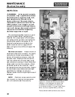
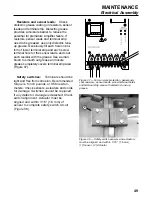
LEDs on the amplifier (Figure 36) will indi-
cate the status of the system:
WARNING:
The amplifier must be
properly wired to function correctly. If
an amplifier or sensor is replaced,
consult the manufacturer’s literature
for complete wiring instructions.
Both green “relay condition” LEDs
are illuminated:
all circuits are closed
and machine is ready for operation.
No LEDs are illuminated:
verify power
to terminals L1 and L2. If there is power
and the LEDs are not illuminated, turn the
power disconnect/lockout switch to “O”
(OFF) and lock out power source.
Remove fuses (see Figure 36) and check
with ohmmeter. Replace faulty fuse. If
problem persists, contact Urschel
Laboratories.
Red “relay condition” LEDs and any of
the red “switch output” LEDs are illu-
minated:
the circuit for the sensor or
resistor assigned to that location is open.
If red “switch output” LEDs which corre-
spond to a sensor are illuminated, discon-
nect and lock out the power source, and
perform the safety switch inspection (see
“Safety switches”, page 49). If red “switch
output” LEDs which correspond to a resis-
tor are illuminated, disconnect and lock
out the power source, verify the resist-
ance value of the resistor and check the
connection for tightness (5 inch pounds or
0.56 newton-meters). Turn power discon-
nect/lockout switch to “I” (ON). If LEDs
remain lit, contact Urschel Laboratories.
Both red “relay condition” LEDs are
illuminated and the red “attention”
LED is flashing:
the amplifier has
detected a fault. To reset the system,
turn the power disconnect/lockout switch
to “O” (OFF) and lock out power source.
Perform safety switch inspection (see
“Safety switches”, page 49). Turn power
disconnect/lockout switch to “I” (ON). If
problem persists, contact Urschel
Laboratories.
WARNING:
A qualified trained
person must always perform the safety
switch system test before operating the
machine. See “Safety Switch System
Test”, page 14.
MAINTENANCE
Electrical Assembly
2
5
6
4
8
3
7
1
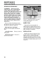
Figure 36 — Amplifier. (1) Fuses, (2) Relays,
(3) Sensor Leads, (4) Resistors, (5) Green “Relay
Condition” LEDs, (6) Red “Relay Condition” LEDs,
(7) Red “Attention” LED, (8) Red “Switch Output” LEDs
Summary of Contents for COMITROL 2100
Page 2: ......
Page 28: ...Addendum A 26 This page intentionally left blank...
Page 84: ...6 This page intentionally left blank...
Page 94: ...16 This page intentionally left blank...
Page 95: ...17 GENERAL INFORMATION...
Page 101: ...23 INSTALLATION...
Page 104: ...26 This page intentionally left blank...
Page 110: ...32 This page intentionally left blank...
Page 131: ...53 PARTS...
Page 132: ...54 This page intentionally left blank...
Page 134: ...56 PARTS Tools See the Addendum for updated information...
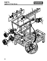
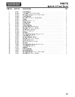
Page 138: ...60 PARTS Agitator Feed Screw See the Addendum for updated information...
Page 146: ...PARTS Motor and Drive Parts 68 See the Addendum for updated information...
Page 148: ...PARTS Electrical Assembly NEMA 70 See the Addendum for updated information...
Page 152: ...PARTS Electrical Assembly CE compliant 74 See the Addendum for updated information...
Page 156: ...78 PARTS Electrical Assembly Switches See the Addendum for updated information...
Page 165: ......

