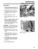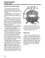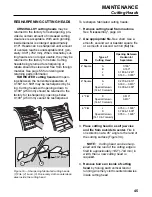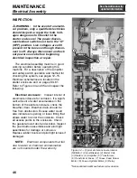
INSPECTION
All parts should be cleaned, inspected for
serviceability, and repaired or replaced if
necessary.
Cutting Head:
Clean thoroughly with
water or cleaning solution and a stiff brush.
Use compressed air to remove any remain-
ing product. Inspect for damage or wear
(see “Cutting Heads”, pages 44 & 45).
NOTE:
Never use a wire brush or
sandpaper to clean cutting parts.
Seal and Seal Cover:
Inspect for wear
or damage and replace if necessary.
Feed Adapter and “O” Ring:
Remove
“O” ring and clean groove in feed adapter.
Inspect “O” ring and replace if necessary.
Feed Screw and Agitator:
Inspect
flights on feed screw and bearing surfaces
for nicks and burrs. File or hone if neces-
sary. Inspect pins in drive shaft ends of feed
screw and agitator for looseness or break-
age.
Bearings and Thrust Bearings:
Inspect for wear and cracks. Replace if nec-
essary.
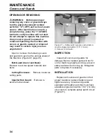
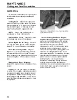
Impeller:
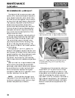
Clean and inspect for damage
or wear. When impeller inserts become worn
(rounded on leading edge), impeller should
be replaced or returned to the factory for re-
tipping (Figure 29). If impeller is worn exces-
sively and insert seats are damaged, it must
be replaced.
Seal in Cutting Head and Ring on
Impeller Mounting Hub:
Approximately
every six months the seal in the cutting
head support and its mating ring on the
impeller mounting hub should be
inspected for wear. With all cutting parts
removed, remove the fastener in the
center of the impeller mounting plate and
slide the mounting hub from the motor
shaft (see page 62). If necessary, remove
impeller mounting plate and use a gear
puller to remove hub. Inspect seal and
mating ring for cracking and wear.
Replace if necessary. Mating surfaces
must be clean and free of nicks and
scratches. Use an anti-seize compound on
motor shaft when reassembling to aid in
future removal of hub.
42
MAINTENANCE
Cutting and Feed Assemblies
Figure 29 — Repairable (left) and non-repairable
(right) Dio-cut impeller
Summary of Contents for COMITROL 2100
Page 2: ......
Page 28: ...Addendum A 26 This page intentionally left blank...
Page 84: ...6 This page intentionally left blank...
Page 94: ...16 This page intentionally left blank...
Page 95: ...17 GENERAL INFORMATION...
Page 101: ...23 INSTALLATION...
Page 104: ...26 This page intentionally left blank...
Page 110: ...32 This page intentionally left blank...
Page 131: ...53 PARTS...
Page 132: ...54 This page intentionally left blank...
Page 134: ...56 PARTS Tools See the Addendum for updated information...
Page 138: ...60 PARTS Agitator Feed Screw See the Addendum for updated information...
Page 146: ...PARTS Motor and Drive Parts 68 See the Addendum for updated information...
Page 148: ...PARTS Electrical Assembly NEMA 70 See the Addendum for updated information...
Page 152: ...PARTS Electrical Assembly CE compliant 74 See the Addendum for updated information...
Page 156: ...78 PARTS Electrical Assembly Switches See the Addendum for updated information...
Page 165: ......

