10
SAFETY
Protective Devices
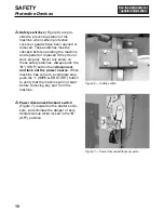
Safety switches
(Figure 6) are pro-
vided to prevent operation of the
machine when certain protective
covers or guards have been opened or
removed. These switches must be
checked before operating the machine
and repaired or replaced if they do not
work properly. Never rely solely on
these safety switches. Always push the
“
O
” (STOP) button then
disconnect
and lock out the power source.
When
machine has come to a complete stop,
push the “I” (IMPELLER START) button
to verify that the machine will not start
before removing any part from the
machine.
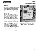
Power disconnect/lockout switch
(Figure 7), located on the starter enclo-
sure, will eliminate the danger of acci-
dental start-up when locked in the “
O
”
(OFF) position.
Figure 6 — Safety switch
Figure 7 — Power disconnect/lockout switch
Summary of Contents for COMITROL 2100
Page 2: ......
Page 28: ...Addendum A 26 This page intentionally left blank...
Page 84: ...6 This page intentionally left blank...
Page 94: ...16 This page intentionally left blank...
Page 95: ...17 GENERAL INFORMATION...
Page 101: ...23 INSTALLATION...
Page 104: ...26 This page intentionally left blank...
Page 110: ...32 This page intentionally left blank...
Page 131: ...53 PARTS...
Page 132: ...54 This page intentionally left blank...
Page 134: ...56 PARTS Tools See the Addendum for updated information...
Page 138: ...60 PARTS Agitator Feed Screw See the Addendum for updated information...
Page 146: ...PARTS Motor and Drive Parts 68 See the Addendum for updated information...
Page 148: ...PARTS Electrical Assembly NEMA 70 See the Addendum for updated information...
Page 152: ...PARTS Electrical Assembly CE compliant 74 See the Addendum for updated information...
Page 156: ...78 PARTS Electrical Assembly Switches See the Addendum for updated information...
Page 165: ......


